The Internet
explained from first principles
Cite this article
You can cite this article in various citation styles as follows:
| MLA: | Etter, Kaspar. “The Internet explained from first principles.” Explained from First Principles, 5 Aug. 2020, https://explained-from-first-principles.com/internet/. Accessed . |
|---|---|
| CMOS: | Etter, Kaspar. “The Internet explained from first principles.” Explained from First Principles, August 5, 2020. Accessed . https://explained-from-first-principles.com/internet/. |
| APA: | Etter, K. (2020, August 5). The Internet explained from first principles. Explained from First Principles. Retrieved , from https://explained-from-first-principles.com/internet/ |
| IEEE: | K. Etter, “The Internet explained from first principles,” Explained from First Principles, Aug. 5, 2020. [Online]. Available: https://explained-from-first-principles.com/internet/. [Accessed: ]. |
| BibTeX: |
@misc{etter_2020_the_internet,
title = {The Internet explained from first principles},
url = {https://explained-from-first-principles.com/internet/},
journal = {Explained from First Principles},
author = {Etter, Kaspar},
date = {2020-08-05},
year = {2020},
month = {Aug},
day = {5},
edition = {2026-02-10},
urldate = {}
}
|
If you are worried about the persistence of this website, you can link to the latest snapshot of the Internet Archive instead.
If you are visiting this website for the first time, then please first read the front page, where I explain the intention of this blog and how to best make use of it. As far as your privacy is concerned, all data entered on this page is stored locally in your browser unless noted otherwise. While I researched the content on this page thoroughly, you take or omit actions based on it at your own risk. In no event shall I as the author be liable for any damages arising from information or advice on this website or on referenced websites.
Preface
I wrote this article to introduce the Internet to a non-technical audience. In order to get everyone on board, I first explain basic concepts, such as communication protocols, network topologies, and signal routing. The section about Internet layers becomes increasingly technical and peaks with a deep dive into DNSSEC. If the beginning is too elementary for you, then just skip ahead to more interesting sections.
Due to the nature of the topic, this article contains a lot of acronyms. Many of them are three-letter acronyms (TLA), but some are longer, which makes them extended three-letter acronyms (ETLA). While I introduce all acronyms before using them, you can simply hover over a TLA or an ETLA with your mouse if you forgot what they stand for. If you are reading this on a touch device, you have to touch the acronym instead.
Let’s get right into it: What is a protocol?
Update
In February 2026, I made the IP geolocation tool more robust, supported IPv6 addresses, and added or significantly modified the following information boxes: Internet Protocol version 6 (IPv6), QUIC, public-key encryption, Wi-Fi Protected Access (WPA), capturing network traffic, Domain Name System Security Extensions (DNSSEC) (including an improved zone walking tool and how to compute digests), DNS stub resolvers, secure DNS connections, and DNS configuration recommendations.
Communication protocol
Communication diagram
A communication protocol specifies how two parties can exchange information for a specific purpose. In particular, it determines which messages are to be transmitted in what order. If the two parties are computers, a formal, well-defined protocol is easiest to implement. In order to illustrate what is going on, however, let’s first look at an informal protocol, also known as etiquette, which we’re all too familiar with:
This is a sequence diagram. It highlights the temporal dimension of a protocol in which messages are exchanged sequentially.
Communication parties
It also illustrates that communication is commonly initiated by one party, whereby the recipient responds to the requests of the initiator. Please note that this is only the case for one-to-one protocols, in which each message is intended for a single recipient.
Broadcasting and information security
There are also one-to-many protocols for broadcasting. These are typically one-way protocols, in which the recipients do not acknowledge the receipt of the transferred data. Examples for such protocols are analog radio or churches ringing their bells to indicate the time of day. Both in the case of a single recipient and in the case of a broad target audience, anyone with access to the physical medium and the right sensors receives the signal. The difference is simply that, in the former case, entities ignore the messages which are not addressed to them. If the messages are not encrypted, others can still read them, though. And if the messages are not authenticated, a malicious party might be able to alter them in transit. Even when messages are encrypted and authenticated, their exchange can still be interrupted, by not relaying some messages or by jamming the signal. The properties Confidentiality, Integrity, and Availability form the so-called CIA triad of information security.
Communication channel
The above greeting protocol is used among humans to establish a communication channel for a longer exchange. In technical jargon, such an exchange in preparation for the actual communication is called a handshake. The greeting protocol checks the recipient’s availability and willingness to engage in a conversation. When talking to someone you have never spoken before, it also ensures that the recipient understands your language. I’ve chosen these two examples for their figurative value. Why we actually greet each other is mainly for different reasons: To show our good intentions by making our presence known to each other, to signal sympathy and courtesy by asking the superficial question, and to indicate our relative social status to each other and to bystanders. Another benefit of asking such a question is that, even though it’s very shallow, it makes the responder more likely to do you a favor due to the psychological effect of commitment and consistency.
Handling of anomalies
Protocol deviation
Since your communication partner can be erratic, a protocol needs to be able to handle deviations:
Data corruption
Sometimes, data becomes unintelligible in transit, for example due to a lot of background noise:
In order to detect transmission errors, computers typically append a checksum to each message, which the recipient then verifies. The need to retransmit messages can be reduced by adding redundancy to messages so that the recipient can detect and correct small errors on their own. A simple and very inefficient way of doing this is to repeat the content within each message several times.
Connection loss
It can also happen that a party loses their connection permanently, for example by moving too far away for the signal to reach the recipient. Since a conversation requires some attention from the communication partner, abandoning a conversation unilaterally without notifying the other party can be misused to block them from talking to someone else for some time. In order to avoid binding resources for a prolonged period of time and thereby potentially falling victim to a so-called denial-of-service attack, computers drop connections after a configurable duration of inactivity:
Network latency
Other times, your communication partner is simply slow, which needs to be accommodated to some degree:
Out-of-order delivery
The following rarely occurs between humans but as soon as messages are passed over various hops, such as forwarding notes among pupils in a classroom, they can arrive out of order:
The solution for this is to enumerate all messages, to reorder them on arrival, and to ask the other party to retransmit any missing messages, as we saw above.
Lack of interoperability
Besides defining the syntax (the format), the semantics (the meaning), and the order of the messages, a protocol should also specify how to handle anomalies like the above. Ambiguity in a standard and willful deviation therefrom result in incompatibilities between different implementations. In combination with a lack of established standards in many areas, which often leads to uncoordinated efforts by various parties, incompatibilities are quite common in computer systems, unfortunately. This causes a lot of frustration for users and programmers, who have to find workarounds for the encountered limitations, but this cannot be avoided in a free market of ideas and products.
Network topologies
Communication network
In practice, there are almost always more than two parties who want to communicate with each other. Together with the connections between them, they form a communication network. For the scope of this article, we’re only interested in symmetric networks, where everyone who can receive can also send. This is not the case for analog radio and television networks, where signals are broadcasted unidirectionally from the sender to the receivers. In the case of our symmetric networks, two entities are part of the same network if they can communicate with each other. If they cannot reach each other, they belong to separate networks.
Nodes and links
Nodes are the entities that communicate with each other over communication links. We can visualize this as follows:
The terminology is borrowed from graph theory, where nodes are also called vertices and links are also called edges. The technical term for the structure of a network is topology. Different arrangements of nodes and links lead to different characteristics of the resulting network.
Fully connected network
A network is said to be fully connected if every node has a direct link to every other node:
In graph theory, such a layout is known as a complete graph. Fully connected networks scale badly as the number of links grows quadratically with the number of nodes. You might have encountered the formula for the number of links before: n · (n − 1) / 2, with n being the number of nodes in the network. As a consequence, this topology is impractical for larger networks.
Star network
The number of links can be reduced considerably by introducing a central node, which forwards the communication between the other nodes. In such a star-shaped network, the number of links scales linearly with the number of nodes. In other words, if you double the number of nodes, you also double the number of links. In a fully connected network, you would have quadrupled the number of links. For now, we call the newly introduced node a router. As we will see later on, such a relaying node is called differently depending on how it operates. Nodes that do not forward the communication of others form the communication endpoints of the network.
While a star network scales optimally, it is by definition completely centralized. If the nodes belong to more than one organization, this topology is not desirable as the central party exerts total control over the network. Depending on its market power, such a party can increase the price for its service and censor any communication it doesn’t like. Additionally, the central node becomes a single point of failure: If it fails for whatever reason, the whole network stops working. Since this lowers the availability of the network, the star topology should not just be avoided for political but also for technical reasons.
Mesh network
We can avoid these drawbacks by increasing the number of nodes which forward the communication between the endpoints:
In this graph, any of the three routers can go down, and communication is still possible between the nodes that are connected not only to the unavailable router. There are also five links that can break one at a time while leaving all nodes indirectly connected with each other. Such a partially connected network allows for a flexible tradeoff between redundancy and scalability. It is therefore usually the preferred network topology. Furthermore, the node marked with an asterisk is connected to two routers in order to increase its availability. Because of higher costs, this is usually done only for critical systems, which provide crucial services.
Signal routing
Network addresses
Unlike in a fully connected network, where each node can simply pick the right link to reach the desired node, a network with relay nodes requires that nodes can address each other. Even if a router relays each signal on all of its links to other nodes, which would make it a hub instead of a router, the nodes still need a way to figure out whether they were the intended recipient of a message. This problem can be solved by assigning a unique identifier to each node in the network and by extending each transmitted message with the identifier of the intended recipient. Such an identifier is called a network address. Routers can learn on which link to forward the communication for which node. This works best when the addresses aren’t assigned randomly but rather reflect the – due to its physical nature often geographical – structure of the network:
We’re all familiar with hierarchical addresses such as postal codes, which are known as ZIP Codes in the United States, and telephone numbers with their country calling codes. Strictly speaking, the address denotes the network link of a node and not the node itself. This can be seen in the node on the right, which is known as B2 to router B and as C1 to router C. In other words, if a node belongs to several so-called subnetworks, such as B and C in this example, it also has several addresses.
Routing tables
The process of selecting a path between two nodes across a network is called routing. Routers are the nodes which perform the routing. They maintain a routing table so they know on which link to forward the communication for each node:
| Destination | Link | Cost |
|---|---|---|
| A1 | 1 | 4 |
| A2 | 2 | 2 |
| B_ | 3 | 5 |
| B_ | 4 | 8 |
| C_ | 3 | 9 |
| C_ | 4 | 6 |
It contains all the destinations to be reached.
The links are numbered according to the above graphic.
The underscore serves as a placeholder for any value in this position.
This table tells router A, for example, to forward all communications for node A2 on link 2. It doesn’t matter on which link router A receives such communications. The router also keeps track of how costly each route is. The cost can either be in terms of network delay or the economic cost of the transmission, based on what providers charge each other. In this example, router A forwards all communications for nodes starting with C on link 4 because the associated cost is lower than the cost for link 3 via router B.
Forwarding tables
To be precise, the routing table contains all routes, even the ones which aren’t optimal regarding the associated costs. Based on this information, a router constructs the actual forwarding table, which contains only the optimal route for each destination without its cost. This makes the table smaller and the lookup during routing faster, which is important for low latency.
| Destination | Link |
|---|---|
| A1 | 1 |
| A2 | 2 |
| B_ | 3 |
| C_ | 4 |
Routing protocols
Routers and the physical links between them can fail at any time, for example because a network cable is demolished by nearby construction work. On the other hand, new nodes and links are added to communication networks all the time. Therefore, the routing tables of routers need to be updated continuously. Instead of updating them manually, routers communicate changes with each other using a routing protocol. For example, as soon as router A detects that it’s no longer getting a response from router C, it updates its routing table to route all communication to C via B:
| Destination | Link | Cost |
|---|---|---|
| A1 | 1 | 4 |
| A2 | 2 | 2 |
| B_ | 3 | 5 |
| C_ | 3 | 9 |
Signal relaying
A signal can be relayed through a network either with circuit switching or with packet switching.
Circuit switching
In a circuit-switched network, a dedicated communications channel is established between the two parties for the duration of the communication session:
The best-known example of a circuit-switched network is the early telephone network. In order to make a call, a switchboard operator had to connect the wires of the two telephones in order to create a closed circuit. This has the advantage that the delay of the signal remains constant throughout the call and that the communication is guaranteed to arrive in the same order as it was sent. On the other hand, establishing a dedicated circuit for each communication session can be inefficient as others cannot utilize the claimed capacity even when it’s temporarily unused, for example when no one is speaking.
Packet switching
In a packet-switched network, the data to transfer is split into chunks. These chunks are called packets and consist of a header and a payload. The header contains information for the delivery of the packet, such as the network address of the sender and the recipient. Each router has a queue for incoming packets and then forwards each packet according to its routing table or, more precisely, its forwarding table. Apart from these tables, packet-switching routers do not keep any state. In particular, no channels are opened or closed on the routing level.
Since each packet is routed individually, they can take different routes from the sender to the recipient and arrive out of order due to varying delays.
Since no router has a complete view of the whole network, it may happen that packets get stuck in an infinite loop:
In order to avoid wasting network resources, the header of a packet also contains a counter, which is decreased by one every time it passes a router. If this counter reaches zero before the packet arrives at its destination, the router discards the packet rather than forwarding it. Such a counter limits the lifespan of a packet by limiting the number of hops it can take and is thus known as its time-to-live (TTL) value. There are also other reasons why a packet can get lost in the network. For example, the queue of a router might simply be full, which means that additional packets can no longer be stored and must be dropped. Because packets are similar to cars on the road network, some terms are borrowed from the transportation industry: While the capacity of a packet-switched network can be utilized better than the capacity of a circuit-switched network, too much traffic on the network leads to congestion.
Source and destination addresses
Because routers keep no records regarding the route that a packet took, the response from the recipient has to include the address of the original sender. In other words, the sender has to disclose its own address to the recipient in order to be able to get a response. This is why packets always include two addresses: the one of the source and the one of the destination.
Internet layers
The Internet is a global network of computer networks. Its name simply means “between networks”. It is a packet-switched mesh network with only best-effort delivery. This means that the Internet provides no guarantees about whether and in what time a packet is delivered. Internet service providers (ISPs) provide access to the Internet for businesses and private individuals. They maintain proprietary computer networks for their customers and are themselves interconnected through international backbones. The big achievement of the Internet is making individual networks interoperable through the Internet Protocol (IP).
The Internet operates in layers. Each layer provides certain functionalities, which can be fulfilled by different protocols. Such a modularization makes it possible to replace the protocol on one layer without affecting the protocols on the other layers. Because the layers above build on the layers below, they are usually listed in the following order but then discussed in the opposite order:
| Name | Purpose | Endpoints | Identifier | Example |
|---|---|---|---|---|
| Application layer | Application logic | Application-specific resource | Application-specific | HTTP |
| Security layer | Encryption and authentication | One or both of the parties | X.509 subject name | TLS |
| Transport layer | Typically reliable data transfer | Operating-system processes | Port number | TCP |
| Network layer | Packet routing across the Internet | Internet-connected devices | IP address | IP |
| Link layer | Handling of the physical medium | Network interface controllers | MAC address | Wi-Fi |
(Please note that I made up the security layer; it doesn’t exist in the literature. Additionally, the network layer is also called the Internet layer.)
We’ll discuss each layer separately in the following subsections. For now, you can treat this table as an overview and summary.
Before we dive into the lowest layer, we first need to understand what “building on the layer below” means. Digital data can be copied perfectly from one memory location to another. The implementation of a specific protocol receives a chunk of data, known as the payload, from the layer above and wraps it with the information required to fulfill its purpose in the so-called header. The payload and the header then become the payload for the layer below, where another protocol specifies a new header to be added. Each of these wrappings is undone by the recipient’s implementation of the respective protocol. This can be visualized as follows:
While this graphic is useful to wrap your head around these concepts, it can be misleading in two ways. Firstly, the payload can be transformed by a specific protocol as long as the original payload can be reconstructed by the recipient. Examples for this are encryption and redundant encoding for automatic error detection and correction. Secondly, a protocol can split a payload into smaller chunks and transfer them separately. It can even ask the sender to retransmit a certain chunk. As long as all the chunks are recombined on the recipient side, the protocol above can be ignorant about such a process.
As we’ve seen earlier, a lot of things can go wrong in computer networks. In the following subsections, we’ll have a closer look on how protocols compensate for the deficiencies of the underlying network. Before we do so, we should talk about standardization.
Request for Comments (RFC)
When several parties communicate with each other, it’s important that they agree on a common standard. Standards need to be proposed, discussed, published, and updated to changing circumstances. I’m not aware of any laws that impose specific networking standards outside of governmental agencies. The Internet has an open architecture, and technology-wise, you’re free to do pretty much anything you want. This doesn’t mean, though, that others will play along. If different companies shall adopt the same standards to improve interoperability, it’s very useful to have independent working groups, in which proposed standards are discussed and approved. For Internet-related standards, such an open platform is provided by the Internet Engineering Task Force (IETF) with organizational and financial support from the Internet Society (ISOC). Workshop participants and managers are typically employed by large tech companies, which want to shape future standards.
The IETF publishes its official documents as Requests for Comments (RFCs). This name was originally chosen to avoid a commanding appearance and to encourage discussions. In the meantime, early versions of potential RFCs are published as Internet Drafts, and RFCs are approved only after several rounds of peer review. RFCs are numbered sequentially, and once published, they are no longer modified. If a document needs to be revised, a new RFC with a new number is published. An RFC can supersede earlier RFCs, which are then obsoleted by the new RFC. Sometimes, RFCs are written after the documented technique has already gained popularity. Even though the most important Internet protocols are specified in RFCs, their conception and style is much more pragmatic than similar documents of other standards organizations. The first RFC was published in 1969. Since then, almost 10’000 RFCs have been published. Not all RFCs define new standards, some are just informational, some describe an experimental proposal, and others simply document the best current practice.
Link layer
Protocols on the link layer take care of delivering a packet over a direct link between two nodes. Examples of such protocols are Ethernet and Wi-Fi. Link-layer protocols are designed to handle the intricacies of the underlying physical medium and signal. This can be an electric signal over a copper wire, light over an optical fiber or an electromagnetic wave through space. The node on the other end of the link, typically a router, removes the header of the link layer, determines on the network layer on which link to forward the packet, and then wraps the packet according to the protocol spoken on that link. Link-layer protocols typically detect bit errors caused by noise, interference, distortion, and faulty synchronization. If several devices want to send a packet over the same medium at the same time, the signals collide, and the packets must be retransmitted after a randomly chosen backoff period.
Number encoding
Numbers are used to quantify the amount of something, and just like you can have only more, less, or an equal amount of a quantity, a number must be either larger than, less than, or equal to any other number (as long as we talk about real numbers only). Numbers can therefore be thought of as points on a line. While numbers as concepts exist independently of the human mind (if we assume mathematical realism), we need a way to express numbers when thinking, speaking, and writing about them. We do so by assigning labels and symbols to them according to a numeral system. For practical reasons, we have to rely on a finite set of symbols to represent an infinite set of numbers. To make this possible, we have to assign meaning to the order, position, and/or repetition of symbols. With the exception of tally marks, only the positional notation is relevant nowadays.
In positional notation, you have an ordered list of symbols, representing the values from zero to the length of the list minus one. In the commonly used decimal numeral system, there are ten symbols, also called digits: 0, 1, 2, 3, 4, 5, 6, 7, 8, and 9. (The name “digit” comes from the Latin “digitus”, which means finger.) As soon as you have used up all the symbols, you create a new position, usually to the left. The represented number is the index of the symbol in this new position multiplied by the length of the list plus the index of the symbol in the initial position. Each time you went through all the symbols in the right position, you increment the left position by one. Two positions of ten possible symbols allow you to represent 102 = 100 numbers. Since zero is one of them, you can encode all numbers from 0 to 99 with these two positions. The symbol in the third position counts how many times you went through the 100 numbers. It is thus multiplied by 102 before being added up. The symbol in the fourth position is multiplied by 103, and so on. All of this should be obvious to you. However, you might not be familiar with using less than or more than ten symbols.
The binary numeral system uses, as the name suggests, only two symbols, typically denoted as 0 and 1. You count according to the rules described above: After 0 and 1 comes 10 and 11, which in turn are followed by 100, 101, 110, and 111. Each position is called a bit, which is short for “binary digit”. Just as with decimal numbers, the most significant bit is on the left, the least significant bit on the right. Since there are only two elements in the list of symbols, the base for exponentiation is 2 instead of 10. If we count the positions from the right to the left starting at zero, each bit is multiplied by two raised to the power of its position. For example, 1101 in binary (usually written as 11012) is 1 · 23 + 1 · 22 + 0 · 21 + 1 · 20 = 8 + 4 + 0 + 1 = 13 in decimal. 4 bits allow you to represent 24 = 16 numbers, and 8 bits allow you to represent 28 = 256 numbers.
Virtually all modern computers use the binary numeral system because each bit can be encoded as the presence or absence of a physical phenomenon, such as voltage or electric current. This makes operations on binary numbers quite easy to implement in electronic circuits with logic gates. Since 0 and 1 don’t encode a lot of information, the smallest unit of computer memory that can be addressed to load or store information is typically a byte, which is a collection of eight bits. Instead of the eight bits, a byte is often represented for humans as a number between 0 and 255 or as two hexadecimal symbols. The latter assigns one symbol to four bits. Since 4 bits encode 16 numbers, the 10 digits are supplemented by 6 letters, resulting in the symbols 0, 1, 2, 3, 4, 5, 6, 7, 8, 9, A, B, C, D, E, and F. The F in hexadecimal notation stands for 15 in decimal notation and 1111 in binary notation.
What I just wrote applies only to natural numbers, also called unsigned integers. Negative integers are included by using the leftmost bit for the sign: Positive numbers start with a zero, negative numbers with a one. The actual encoding is a bit more complicated because it is chosen such that the implementation of addition, subtraction, and multiplication is the same for signed and unsigned integers. Floating point numbers are even more complicated and beyond the scope of this article.
Media access control (MAC) address
The media access control (MAC) address is commonly used as the network address on the link layer. It’s a 48-bit number, which is typically displayed as six pairs of hexadecimal digits. (One hexadecimal digit represents 4 bits, so twelve hexadecimal digits represent 48 bits.) MAC addresses are used in Ethernet, Wi-Fi, and Bluetooth to address other devices in the same network. Historically, they were assigned by the manufacturer of the networking device and then remained the same throughout the lifetime of the device. Since this allows your device to be tracked, operating systems started randomizing MAC addresses when scanning for Wi-Fi networks after the revelations by Edward Snowden. According to Wikipedia, MAC address randomization was added in iOS 8, Android 6.0, Windows 10, and Linux kernel 3.18.
Hubs, switches, and routers
When I talked about network topologies, I simply called relaying nodes “routers”, but there are actually three types of them:
- A hub simply relays all incoming packets to all other links.
- A switch remembers which MAC address it encountered on which of its links and forwards incoming packets only to their intended recipients. Like a hub, a switch also operates only on the link layer. To the devices in the network, it still seems as if they are directly connected to each other.
- A router inspects and forwards packets on the network layer based on its forwarding table. It can thereby connect several independent networks. Your Wi-Fi router, for example, routes packets within your local network but also between your local network and the network of your Internet service provider. As we will cover in the next subsection, it also provides important services, such as DHCP and NAT.
Maximum transmission unit (MTU)
Link-layer protocols usually limit the size of the packets they can forward over the link. This limit is known as the maximum transmission unit (MTU) of the link. For example, the MTU of Ethernet is 1500 bytes. If a packet is larger than the MTU, it is split into smaller fragments by the network layer. If the network drops any of the fragments, then the entire packet is lost.
IP over Avian Carriers (IPoAC)
Written as an April Fools’ joke, RFC 1149 describes a method for delivering packets on the link layer using homing pigeons. While this method is of no practical importance, it shows the flexibility of the Internet layers and is well worth a read.
Network layer
The purpose of the network layer is to route packets between endpoints. It is the layer that ensures interoperability between separate networks on the Internet. As a consequence, there’s only one protocol which matters on this layer: the Internet Protocol (IP). If you want to use the Internet, you have to use this protocol in one of its versions. As we’ve seen earlier, packet switching provides only unreliable communication. It is left to the transport layer to compensate for this.
Internet Protocol version 4 (IPv4)
The first major version of the Internet Protocol is version 4 (IPv4), which has been in use since 1982 and still accounts for a bit more than half of all Internet traffic in 2025. It uses 32-bit numbers to address endpoints and routers, which are written as four numbers between 0 and 255 separated by a dot. These IP addresses reflect the hierarchical structure of the Internet, which is important for efficient routing. They are assigned by the Internet Assigned Numbers Authority (IANA), which belongs to the American Internet Corporation for Assigned Names and Numbers (ICANN), and by five Regional Internet Registries (RIR). If you’re interested, you can check out the current IPv4 address allocation. There are just under 4.3 billion IPv4 addresses (232 = 4’294’967’296), which are quite unevenly distributed among countries. Given the limited address space, we’re running out of IPv4 addresses. In order to deal with the IPv4 address exhaustion, the Internet Protocol version 6 (IPv6) has been developed.
Internet Protocol version 6 (IPv6)
The Internet Protocol version 6 (IPv6) was first specified
in RFC 1883 in 1995
and has been in use since 2003.
It uses 128-bit addresses,
which are represented as eight groups of four hexadecimal digits,
with the groups separated by colons.
An example IPv6 address is 2001:0DB8:0000:0000:1A2B:0000:0000:0003.
(RFC 3849
reserves the IPv6 address prefix
2001:0DB8 for use in documentation.)
In order to make searching and comparing IPv6 addresses in text easier,
RFC 5952 defines a
canonical form:
- No leading zeros: Omit leading zeros in each group but retain at least one digit.
We thus have
2001:DB8:0:0:1A2B:0:0:3. - Lowercase: Use lowercase letters for the hexadecimal digits.
The example address becomes
2001:db8:0:0:1a2b:0:0:3. - Zero compression: Replace the longest sequence of consecutive
0groups with::. Shorten as many groups as possible and don’t compress a single0group. If several sequences of consecutive0groups have the same length, compress the first one. The::may appear only once in an IPv6 address, but it can appear at the beginning or the end of an address. Putting these rules together,2001:0DB8:0000:0000:1A2B:0000:0000:0003should be rendered in text as2001:db8::1a2b:0:0:3.
As IPv6 isn’t interoperable with IPv4, the transition has been slow but steady, reaching almost 50% of traffic in 2025.
IP geolocation
Because the Internet isn’t just a protocol but also a physical network, which requires big investments in infrastructure like fiber-optic cables, Internet service providers (ISPs) used to operate regionally. (SpaceX’s Starlink is starting to change that). To facilitate the routing of packets, they get assigned an IP address range for their regional network. This allows companies to build databases that map IP addresses to their approximate geographic location. Unless you use a virtual private network (VPN) or an overlay network for anonymous communication, such as Tor, you reveal your approximate location to every server you communicate with. Websites such as streaming platforms use this information to restrict the content available to you based on the country you’re visiting the site from due to their copyright licensing agreements with content producers.
One company with such a geolocation database is IPinfo.io. Using their free API, I can tell roughly where you are. Just leave the field in the following tool empty and click on “Locate” for this. (If you’re visiting this website via a cellular network or a satellite, the result will be less accurate.) Alternatively, enter an IPv4 or IPv6 address of interest to see its approximate location.
Network performance
The performance of a network is assessed based on the following measures:
- Bandwidth indicates how much data can be transferred in one direction in a given amount of time. Unlike memory, which is measured in bytes, bandwidth is usually measured in bits per second, which is written as bit/s or bps. As always, multiples of the unit can be denoted with the appropriate prefix, such as M for mega (106) in Mbit/s or Mbps.
- Latency indicates how long it takes for a single bit to reach the recipient. Latency is usually determined by sending a tiny message to the recipient and measuring the time until a tiny response is received. The result is called the round-trip time (RTT) to that particular destination, which includes the one-way delay (OWD) in both directions and the time it took the recipient to process the request. Have a look at the next two boxes for more information on this.
- Jitter is the undesired variation in the latency of a signal. On the link layer, such a deviation from the periodic clock signal is caused by the properties of the physical medium. The term is sometimes also used to refer to variation in packet delay.
- The bit error rate indicates the percentage of bits that are flipped during the data transfer. As mentioned earlier, data corruption has to be detected and corrected by network protocols.
The term throughput is sometimes used interchangeably with bandwidth. Other times, it’s used to refer to the actual rate at which useful data is being transferred. The effective throughput is lower than the maximum bandwidth due to the overhead of headers, packet loss and retransmission, congestion in the network, and the delay for acknowledgements by the recipient.
More bandwidth doesn’t reduce the latency of Internet communication, which is the crucial factor for applications such as algorithmic trading and online gaming, where latency is called lag. The design of a protocol impacts its performance: The more messages that need to be exchanged in a session, the less throughput you get over long distances due to the many round trips.
You can measure the speed of your Internet connection with tools such as speedtest.net. A high download speed is important for watching high-definition videos and downloading large files, such as computer games and software updates. A high upload speed is important for participating in video calls and uploading large files, such as videos or hundreds of pictures. As a rule of thumb, you can divide the number of megabits per second by ten to get a rough estimate for actual megabytes per second due to the aforementioned overhead. Please keep in mind that Internet communication is routed over many links and that any of the links, including the Wi-Fi link to your own router, can limit the overall performance. For example, if a server you interact with has a slow connection or is very busy, then paying more for a faster Internet at your end won’t improve the situation.
Propagation delay
The physical limit for how fast a signal can travel is the speed of light in vacuum, which is roughly 300’000 km/s or 3 · 108 m/s. It takes light 67 ms to travel halfway around the Earth and 119 ms to travel from geostationary orbit to Earth. While this doesn’t sound like a lot, propagation delay is a real problem for applications where latency matters, especially because a signal often has to travel back and forth to be useful. One party typically reacts to information received from another party, hence it takes a full round trip for the reaction to reach the first party again. The speed at which electromagnetic waves travel through a medium is slower than the speed of light in vacuum. The speed of a light pulse through an optical fiber is ⅔ of the speed of light in vacuum, i.e. 2.0 · 108 m/s. A change of electrical voltage travels slightly faster through a copper wire at 2.3 · 108 m/s. When costs allow it, optical fibers are often preferred over copper wire because they provide higher bandwidth over longer distances with less interference before the signal needs to be amplified. It remains to be seen whether satellite constellations in low-Earth-orbit (LEO), such as SpaceX’s Starlink, will be able to provide lower-latency transcontinental connections by using laser communication in space. If they succeed, the financial industry will happily pay whatever it costs to use it.
Internet Control Message Protocol (ICMP)
The Internet Control Message Protocol (ICMP) is used by routers to send error messages to the sender of a packet, for example, when a host cannot be reached or when a packet exceeds its time to live (TTL). ICMP messages are attached to an IP header, in which the IP protocol number is set to 1 according to RFC 792. ICMP complements the Internet Protocol on the network layer. It has various message types, with two of them being commonly used to determine the round-trip time to a network destination. The network utility to do so is called ping. It sends several echo requests and waits for the echo replies before reporting statistics on packet loss and round-trip times:
The first line consists of the command and options that I entered, all the subsequent lines are output by the ping utility.
Round-trip times within the same geographical area are typically below 10 ms, whereas it takes around 80 to 100 ms
to the US East Coast and around 150 to 170 ms to the US West Coast and back from my place in central Europe.
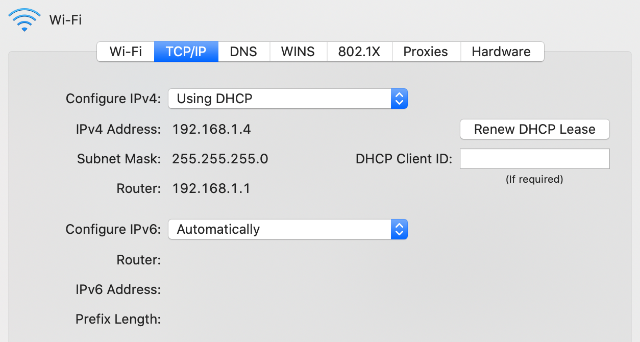
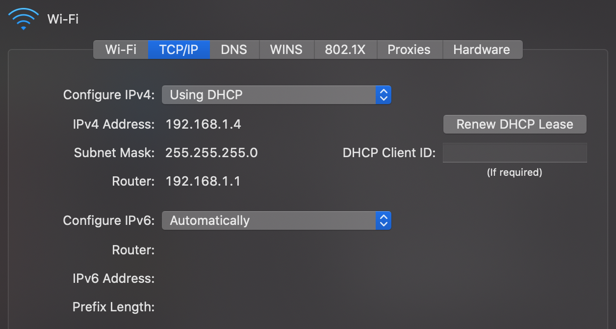
Dynamic Host Configuration Protocol (DHCP)
Unlike the MAC address, which at least historically always stayed the same, the IP address of your device is different for every network it joins as IP addresses are allocated top-down to allow for efficient routing between networks. Instead of configuring the IP address manually every time you join another network, your device can request an IP address from the network’s router using the Dynamic Host Configuration Protocol (DHCP) as specified in RFC 2131. DHCP is an application layer protocol.
Address Resolution Protocol (ARP)
When devices want to communicate with each other in the same network, they need to know the MAC address of the other devices in order to address them on the link layer. The Address Resolution Protocol (ARP) resolves IP addresses to MAC addresses in the local network. By using a special MAC address which is accepted by all devices on the local network, any network participant can ask, for example, “Who has the IP address 192.168.1.2?”. The device which has this IP address responds, thereby sharing its MAC address.
Transport layer
Operating systems
Before we can discuss the transport layer, we first need to talk about operating systems. The job of an operating system (OS) is to manage the hardware of a computer. The hardware of a computer includes:
- processors, such as the central processing unit (CPU) and the graphics processing unit (GPU),
- memory, such as volatile memory and non-volatile memory like your solid-state drive (SSD),
- input/output (I/O) devices, such as a keyboard and a mouse for input, a monitor and speakers for output,
- as well as a network interface controller (NIC) to communicate with other devices on the same network.
An operating system serves the following three purposes:
- Abstraction: It simplifies and standardizes access to the hardware, making it easier for engineers to develop software for several computing platforms.
- Duplication: It provides the same hardware to all programs running on the same computer, while giving each program the illusion that it has the hardware just for itself.
- Protection: It enforces restrictions on the behavior of programs. For example, it can deny access to the webcam or certain parts of the file system unless the user has granted the necessary permissions.
Port numbers
When a program is being executed, it is called a process. This distinction is important because the same program can be executed several times in parallel, which results in several processes until they terminate. Since more than one process may want to use the network connection at the same time, the operating system needs a way to keep the traffic of different processes apart. The label used for this purpose is a 16-bit integer known as port number. When a process sends a request to another device, the operating system chooses an arbitrary but still unused port number and encodes it as the source port in the transport-layer wrapping of the outgoing packet. The recipient then has to include the same port number as the destination port in its response. When the operating system of the requester receives this response, it knows which process to forward the incoming packet to because it kept track of which port numbers it used for which process.
But how does the operating system of the recipient know what to do with the incoming packet? The answer is registration and convention. A process can ask the operating system to receive all incoming packets which have a certain destination port. If no other process has claimed this port before, the operating system grants this port to the process. A port can be bound to at most one process. If it is already taken, then the operating system returns an error. Ports are distributed on a first-come, first-served basis. To claim port numbers below 1024, processes need a special privilege, though. Which port to claim as a receiving process is handled by convention. Each application layer protocol defines one or several default ports to receive traffic on. Wikipedia has an extensive list of established port numbers.
Client-server model
A server
is just a process
registered with the operating system
to handle incoming traffic on a certain port.
It does this to provide a certain service,
which is then requested by so-called clients.
This is called the client-server model,
which contrasts with a peer-to-peer architecture,
where each node equally provides and consumes the service.
The communication is always initiated by the client.
If the server makes a request itself,
it becomes the client in that interaction.
A server is typically accessed via a network, such as the Internet,
but it can also run on the same machine as its client.
In such a case, the client accesses the server via a so-called loopback,
which is a virtual network interface
where the destination is the same as the source.
The current computer is often referred to as localhost.
There is also a dedicated IP address for this purpose:
127.0.0.1 in the case of IPv4
and ::1 in the case of IPv6.
Transmission Control Protocol (TCP)
The problem with packet-switched networks, such as the Internet, is that packets can get lost or arrive out of order with an arbitrary delay. However, it is desirable for many applications that what the receiver receives is exactly what the sender sent. So how can we get reliable, in-order transfer of data over an unreliable network? This is achieved by the Transmission Control Protocol (TCP), which brings the concept of a connection from circuit-switched networks to packet-switched networks. But unlike connections in circuit-switched networks, TCP connections are handled by the communication endpoints without the involvement of the routers in between.
In order to provide reliable data transfer, both the sending and the receiving process temporarily store outgoing and incoming packets in a buffer. In each direction of communication, the packets are enumerated with a so-called sequence number. For each packet that is being transferred, its 32-bit sequence number is encoded in the TCP header. This allows the recipient to reorder incoming packets which arrived out of order. By including the sequence number up to which they have successfully received all packets from the other party in the TCP header as well, each party lets the other party know that it can remove earlier packets from its buffer. Packets whose receipt is not acknowledged in this way are retransmitted by the sender.
TCP headers also include a checksum to detect transmission errors. On top of that, TCP allows each party to specify how many packets beyond the last acknowledged sequence number they are willing to receive. This mechanism, known as flow control, ensures that the sender does not overwhelm the receiver. Last but not least, the sender slows down its sending rate when too many packets are lost because the network might be overloaded. This feature is called congestion control.
IP address spoofing
In all the protocols we have discussed so far, nothing ensures the authenticity of the transmitted information. For example, an attacker can fake their identity by encoding a different source address into the header of a packet. By posing as someone else, the attacker might gain access to a system that they didn’t have before. This is known as a spoofing attack. On the link layer, it’s called MAC address spoofing, and on the network layer, it’s called IP address spoofing.
Since a router connects different networks, it can block packets that come from one network but have a source address from a different network. For packets coming from the outside but claim to be from the local network, this is referred to as ingress filtering. Ingress filtering protects internal machines from external attackers. For outgoing packets that do not have a source address from the local network, the term is egress filtering. Egress filtering protects external machines from internal attackers. As such, the administrator of the local network has fewer incentives to implement this.
The reason why we’re discussing this under the transport layer and not earlier is that TCP makes the spoofing of IP addresses much more difficult. The problem with encoding a wrong source address is that the recipient sends its responses to that wrong address. This means that unless an attacker also compromised a router close to the recipient, they won’t receive any of the response packets. Therefore, the interaction needs to be completely predictable for the attack to succeed. Before any actual data can be sent, TCP first establishes a connection by exchanging a few TCP packets without a payload. As mentioned earlier, such preliminary communication in preparation for the actual communication is called a handshake. In a TCP handshake, both parties choose the initial sequence number for their outgoing packets at random. As the sequence number consists of 32 bits, which results in more than four billion possibilities, an attacker who doesn’t see the responses from the victim is very unlikely to guess the correct sequence number. Thus, none of the victim’s response packets will be properly acknowledged, which leads to a failed connection on the transport layer before the program on the application layer gets a chance to perform what the attacker wanted.
User Datagram Protocol (UDP)
There is a second important protocol on the transport layer, which I want to mention for the sake of completeness: the User Datagram Protocol (UDP). UDP provides connectionless and thus unreliable communication between processes, encoding only the source and destination port numbers together with a length field and a checksum in its header. It provides none of the other features of TCP, thereby prioritizing fast delivery over reliability. This is useful for streaming real-time data, such as a phone or video call, over the Internet. While the quality of the call deteriorates when too many packets are lost or delayed, there’s no point in insisting on having them delivered as they cannot be played back later. As there is no connection setup and consequently no need for a handshake, UDP can also be used to broadcast information to all devices in the same local network. Protocols based on UDP, such as DNS, are often vulnerable to IP address spoofing, which makes amplification attacks possible.
Network address translation (NAT)
In an effort to conserve IPv4 addresses in order to alleviate the above-mentioned address space exhaustion, all devices in a local network commonly share the same source address when communicating with other devices over the Internet. This is accomplished by requiring that all communication is initiated by devices in the local network and by having the router engage in a technique known as network address translation (NAT). The basic idea is that the router maintains a mapping from the internally used IP address and port number to a port number it uses externally.
| Internal address | Internal port | External port |
|---|---|---|
| 192.168.1.2 | 58’237 | 49’391 |
| 192.168.1.2 | 51’925 | 62’479 |
| 192.168.1.4 | 64’296 | 53’154 |
| … | … | … |
For each outgoing packet, the router checks whether it already has a mapping for the given IP address and source port. If not, it creates a new mapping to a port number it has not recently used in its external communication. The router then rewrites the headers of the outgoing packet by replacing the internal IP address with its own on the network layer and the internal port with the mapped external port on the transport layer. For each incoming packet, the router looks up the packet’s destination port number in its translation table. If found, it replaces the destination address and port of the packet with the found internal values and forwards the packet to the corresponding device in the local network. If no such entry exists, it simply drops the incoming packet. What makes the technique a bit complicated in practice is that the router also has to recompute all the checksums on the transport layer and handle potential fragmentation on the network layer.
From a security perspective, network address translation has the desirable side effect that the router now also acts as a firewall, blocking all unsolicited incoming traffic. This breaks symmetric end-to-end connectivity, though. One of the core principles of the Internet is that any device can communicate with any other device. Given the widespread adoption of NAT, this principle no longer holds nowadays, unfortunately. If you still want to host a server on such a network, you need to configure your router to forward all incoming traffic on a certain port to that machine. This is known as port forwarding. The loss of end-to-end connectivity is also a problem for peer-to-peer applications, which need to circumvent NAT by punching a hole through its firewall or rely on an intermediary server to relay all communication.
Two remarks on the values used in the example translation table above:
- IP addresses starting with 192.168 are reserved for private networks. This address range is often used for local networks behind routers which perform NAT. As a consequence, your network settings might look quite similar to mine.
- Clients can use any port number they like as their source port. If this wasn’t the case, network address translation wouldn’t work. I’ve chosen the values above from the range that IANA suggests for such ephemeral ports, namely 49’152 to 65’535.
Server on your personal computer
I said above that a server is just a process registered with the operating system to handle incoming traffic on a certain port. In particular, no special hardware is required; you can easily run a server on your personal computer. In practice, servers run on hardware optimized for their respective task, of course. For example, since the computers in data centers are administrated remotely most of the time, they don’t need to have a keyboard, mouse, or monitor. But there are also other reasons besides hardware why running a server on your personal computer is not ideal:
- Uptime: A server should be online all the time so that others can reach it at any time. If you host, for example, your personal website on your personal computer, you should no longer switch off your computer. Even restarting your computer after installing some updates makes your website unavailable for a short amount of time.
- Utilization: Unless your website is popular, your computer will be idle most of the time. In a data center, several customers can share the same machine, which makes better use of the hardware as well as electricity.
- Workload: If your website does become popular, your personal computer might no longer be powerful enough to serve it. Professional hosting providers, on the other hand, have experience in balancing increased load across several machines.
- Administration: Keeping a service secure and available requires a lot of time and expertise. While this can be an enjoyable and at times frustrating side project, better leave the monitoring and maintenance of your services to experts.
- Dynamic addresses: Once you set up port forwarding on your router in order to circumvent network address translation, you still face the problems that your computer gets a dynamic IP address from the router and that the router typically gets a dynamic IP address from your Internet service provider (see DHCP). In the local network, you can configure your router to assign always the same IP address to your computer based on its MAC address. As far as your public IP address is concerned, your ISP might offer a static address at a premium. Otherwise, you’d have to use Dynamic DNS.
In conclusion, running a production server on your ordinary computer is possible but not recommended. However, software engineers often run a development server locally on their machine, which they then access via the above-mentioned loopback address from the same machine. This allows them to test changes locally before they deploy a new version of their software.
Firewall
A firewall permits or denies network traffic based on configured rules. The goal is to protect the local network or machine from outside threats. In order to compromise your system, an attacker needs to find a hole in the firewall and a vulnerability in a particular application. Having multiple layers of security controls is known as defense in depth. Depending on the firewall and the configured rules, packets are inspected and filtered on the network, transport, or application layer. If the firewall rules are imposed by someone else, such as a network administrator or the government, users might resort to tunneling their traffic via an approved protocol. Make sure you have the firewall enabled in the network settings of your operating system.
Security layer
All the communication we have seen so far is neither authenticated nor encrypted. This means that any router can read and alter the messages that pass through it. Since the network determines the route of the packets rather than you as a sender, you have no control over which companies and nations are involved in delivering them. The lack of confidentiality is especially problematic when using the Wi-Fi in a public space, such as a restaurant or an airport, because your device simply connects to the wireless access point of a given network with the best signal. Since your device has no way to authenticate the network, anyone who knows the Wi-Fi password can impersonate the network and then inspect and modify your traffic by setting up a fake access point. This is known as an evil twin attack, which also affects mobile phone networks. As a general principle, you should never trust the network layer.
Transport Layer Security (TLS)
Transport Layer Security (TLS) is the main protocol to provide confidential and authenticated communication over the Internet. Its predecessor, Secure Sockets Layer (SSL), was developed at Netscape and released in 1995 as version 2.0. In order to increase acceptance and adoption, SSL was renamed to TLS in 1999 after SSL 3.0. TLS exists in the versions 1.0, 1.1, 1.2, and 1.3. SSL 2.0 and 3.0 as well as TLS 1.0 and 1.1 have been deprecated over time due to security weaknesses and should no longer be used. While it is beyond the scope of this article to explain how the cryptography used in TLS works, this is what it provides:
- Party authentication: The identity of the communicating parties can be authenticated using public-key cryptography. While TLS supports the authentication of both the client and the server, usually only the identity of the server is verified. To this end, the server sends a signed public-key certificate to the client during the TLS handshake. The client then verifies whether the signature was issued by an organization it trusts. (You find more information on this in these boxes.) This allows the client to be fairly confident that it connected to the right server without the communication being intercepted by a man in the middle (MITM). While the client could also present a public-key certificate, the client is more commonly authenticated on the application layer, for example with a username and a password.
- Content confidentiality: The content of the conversation is
encrypted in transit with
symmetric-key cryptography.
The shared key
is generated
by the client and the server during the TLS handshake at the start of the session.
Please note that while the content is encrypted,
a lot of metadata is revealed
to anyone who observes the communication between the two parties.
An eavesdropper learns that
- a TLS connection was established between the two IP addresses,
- the time and duration of the connection, which leaks a lot, given that a response often triggers follow-up connections,
- the rough amount of data that was transferred in each direction,
- and likely the name of the server.
Before TLS 1.3, the server sends its certificate to the client in plaintext.
Even when TLS 1.3 is being used, the client probably sent an unencrypted DNS query beforehand.
Moreover, the eavesdropper can make a reverse DNS lookup of the server’s IP address.
And last but not least, the client typically indicates the desired host name
to the server so that the server knows which certificate to send back.
As of 2025, Encrypted Client Hello (ECH) is being finalized
to encrypt the sensitive parts of the client’s first message, including the server name,
if the server publishes an encryption public key in the
echparameter of anSVCBorHTTPSDNS record. Have a look at this example.
- Message authentication: Each transmitted message is authenticated with a so-called message authentication code. This allows each party to verify that all messages were sent by the other party and that the messages were not modified in transit. (Encryption alone usually does not guarantee the integrity of the encrypted data because encryption generally does not protect against malleability.) What TLS does not provide, however, is non-repudiation. Or put another way: A party can plausibly dispute that it made the statements inside a TLS connection. This is because message authentication codes are symmetric, which means that whoever can verify them can also generate them.
Since TLS requires reliable communication, it uses TCP on the transport layer – or is handled by QUIC over UDP.
QUIC
QUIC, which is pronounced as “quick”, is a modern alternative to using TLS over TCP with the following features among others:
- Combined handshake: When running TLS over TCP, it takes one round trip to establish the TCP connection and another round trip to establish the TLS 1.3 connection inside the TCP connection. (A full TLS 1.2 handshake takes two round trips.) QUIC combines the two handshakes by carrying the bytes of the TLS 1.3 handshake in its first two packets. TLS 1.3 was specified before QUIC in RFC 8446 and could be used by the standardized version of QUIC as is. TLS libraries, on the other hand, had to be adapted to expose the information required by QUIC. TLS 1.3 is an integral part of QUIC, i.e. QUIC cannot be used without it.
- Proper multiplexing: While some protocols which run over TCP, such as HTTP/2 (the second major version of HTTP), allow several documents to be sent in parallel by interleaving them, a missing TCP packet in one document blocks the loading of all the documents. This is known as head-of-line blocking. QUIC solves this problem by using UDP on the transport layer and handling retransmission of lost packets for each stream within the same QUIC connection independently. The advantage over opening several connections to the same server is that the connection setup overhead (the round trip, counterparty authentication, and key agreement) can be shared by several streams, while also allowing some streams to be prioritized over others. To make this possible, QUIC encrypts each packet individually.
- Connection migration: Unlike TCP, which identifies a connection by the local and remote IP addresses and port numbers, QUIC identifies a connection typically by a connection ID in the packet header. This allows QUIC connections to survive network changes, such as switching from a Wi-Fi to a mobile hotspot, whereas TCP connections time out and must be re-established by each client, causing interruptions and overhead.
QUIC was originally developed at Google in 2012 and then standardized by the IETF in May 2021 in RFC 8999, RFC 9000, RFC 9001, and RFC 9002. Originally, QUIC was an acronym for Quick UDP Internet Connections. In the IETF standards, QUIC has become the proper name of the protocol. QUIC is the basis of HTTP/3 (the third major version of HTTP) as specified in RFC 9114 and DNS over QUIC (DoQ) as specified in RFC 9250. HTTP/3 is supported by all major browsers and by around 36% of all websites. Cloudflare (a large content delivery network (CDN)) serves around 31% of its requests over HTTP/3.
While TLS is not mandatory for HTTP/2, browsers support HTTP/2 only over TLS.
Both HTTP/2 and HTTP/3 are served on port 443.
So how does a browser know whether a webserver supports HTTP/3 with all its advantages?
A server can advertise the protocols it supports with a special DNS record.
When connecting to a webserver for the first time,
a browser can check this record or start both an HTTP/2 and an HTTP/3 connection in parallel
and abort the former when the latter succeeds.
Alternatively, a webserver can indicate its support for HTTP/3 with the HTTP response header field
Alt-Svc: h3=":443".
Digital signatures
The essential feature of signatures is that they are easy for the author to produce but hard for others to forge. Since digital information can be duplicated and appended without degradation, a digital signature has to depend on the signed content. Handwritten signatures, on the other hand, are bound to the content simply by being on the same piece of paper/material.
Digital signature schemes consist of three algorithms:
- Key generation: First, the signer chooses a random private key, from which they can compute the corresponding public key. The signer should keep the private key to themself, while the public key can be shared with anyone. Both keys are usually just numbers or pairs of numbers in a certain range. For the digital signature scheme to be secure, it has to be infeasible to derive the private key from the public key. This requires that one-way functions, which are easy to compute but hard to invert, exist. It is widely believed that this is the case, but we have no proof for this yet. An example of such an asymmetric relationship is integer multiplication versus integer factorization. While the former can be computed efficiently, the latter becomes exceedingly hard for large numbers.
- Signing: The signer then computes the signature for a given message using the private key generated in the previous step. The signature is also just a number or a tuple of several numbers. Since the computation of the signature depends on the private key, only the person who knows the private key can produce the signature.
- Verifying: Anyone who has the message, the signature, and the signer’s public key can verify that the signature was generated by the person knowing the corresponding private key.
As you can see from these algorithms, digital signatures rely on a different authentication factor than handwritten signatures. While the security of handwritten signatures relies on something the signer does with their fine motor skills, the security of digital signatures relies on something the signer knows or rather has. In theory, a private key is a piece of information and thus knowledge. In practice, however, a private key is usually too big to remember and thus rather a piece of data that the user has. Since the private key is not inherent to the signer but rather chosen by the signer, digital signatures require that the signer assumes responsibility for the signed statements. This brings us to the next topic: public-key infrastructure.
Public-key infrastructure (PKI)
How do you know that someone took responsibility for all signatures which can be verified with a certain public key if you have never met them in person? In the absence of knowledge like this, you cannot authenticate anyone over an insecure channel. However, if you know the public key of some individuals, you can verify whether or not they signed a certain statement. A statement can be of the form: “Person … told me that their public key is …”. If you know the public key of the person who signed such a statement and if you trust this person to sign only truthful statements, then you just learned the public key of another person. With this technique, you can now authenticate someone you have never met before as long as you have met someone before who met that someone before. For example, if you met Alice at some point and received her public key directly from her, you can authenticate Bob over an untrusted network if Alice met Bob and confirms to you (and everyone else) that a specific public key indeed belongs to Bob. Whether Alice sends the signed statement with this content directly to you or whether Bob presents this signed statement during the conversation with him doesn’t matter. Since you know the public key of Alice, you can verify that only she could produce the signature. In order to make the system scale better, you can decide to also trust Bob’s statements regarding the public key of other people, in particular if Alice decided to trust Bob in this regard. This makes trust transitive: If you trust Alice and Alice trusts Bob, then you also trust Bob.
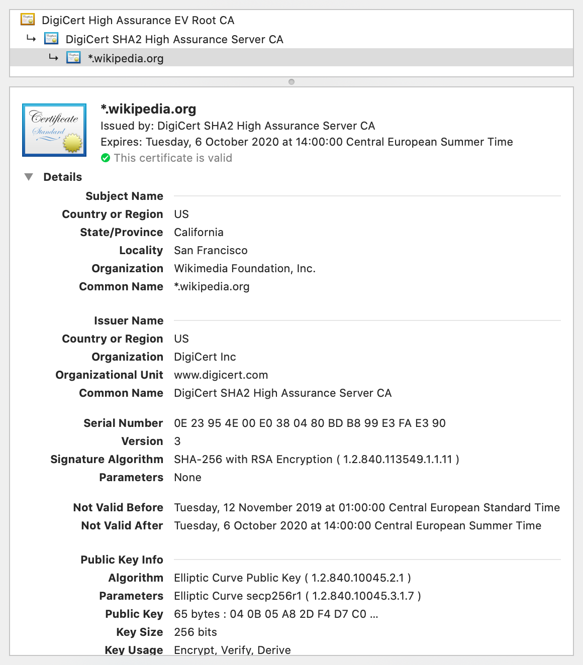
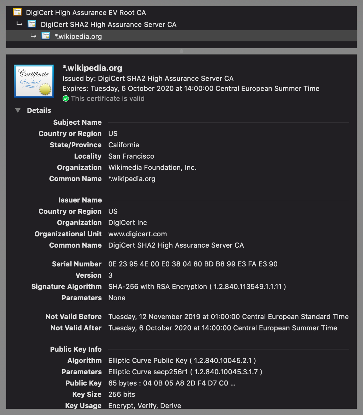
Signed statements of the above form are called public-key certificates. A widely adopted format for public-key certificates is X.509, which is also used in TLS. X.509 certificates are often displayed as follows:
There are two different paradigms for issuing public-key certificates:
- Web of trust: As described above, you start out with no trust and then expand your circle of trust by meeting people and verifying each other’s public key. This is done most efficiently at so-called key-signing parties, where participants verify each other with state-issued identity documents. The big advantage of this paradigm is that it is completely decentralized, requiring no setup and no trusted third party. On the other hand, it demands a lot of diligence from individual users. Additionally, every user has a different view of which identity assertions can be trusted. While this works reasonably well for social applications such as messaging, such a fragmented trust landscape is not ideal for economic interactions.
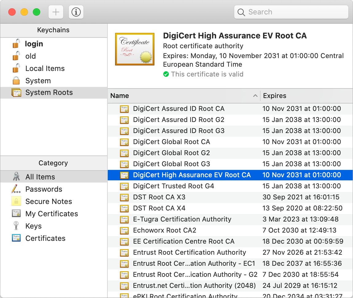
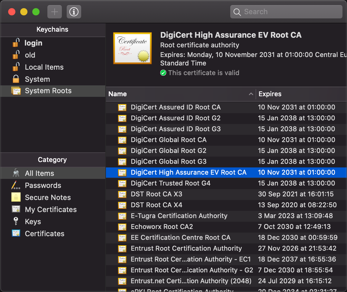
- Certification authorities (CAs): In the other, more common paradigm, manufacturers deliver their devices or operating systems with a preinstalled list of trusted third parties to their customers. An employer might replace or extend this list on corporate devices. These trusted third parties are called certification authorities (CAs). While users can add and remove CAs on their own devices, they rarely do this – and I also recommend against messing with this list, as badly informed changes can compromise the security of your system. Organizations and individuals pay one of these CAs to assert their identity. A preinstalled CA, also known as a root CA, can also delegate the authority to certify to other entities, which are called intermediate CAs. If you have a look at the top of the above screenshot, you see that this is exactly what happened: The root CA DigiCert High Assurance EV Root CA delegated its authority with a signed certificate to the intermediate CA DigiCert SHA2 High Assurance Server CA, which in turn signed that the public key at the bottom of the screenshot, of which only the beginning is displayed by default, belongs to the Wikimedia Foundation as the subject of the certificate. If we check the list of root CAs, we see that DigiCert High Assurance EV Root CA is indeed among them:
As described above, the server sends its certificate to the client during the TLS handshake. By also including the certificate of a potential intermediate CA, the client has all the information needed to authenticate the server. Therefore, CAs don’t have to be reachable over the Internet, which is good for the security of their signing keys and for the reliability of the Internet. There is a lot more to public-key certificates, such as expiration and revocation, but these aspects are beyond the scope of this article.
Public-key encryption
Another use case of public-key cryptography besides digital signatures is encryption. The private key and the public key are generated similarly as before, but a different pair of algorithms (called encryption and decryption) allows anyone to transmit a message, which is called plaintext when it’s not encrypted and ciphertext when it is encrypted, to a recipient so that no one else can read it. I added this box just so that you’re not confused when I use the term public key in the context of encryption.
Wi-Fi Protected Access (WPA)
Wi-Fi Protected Access (WPA) is the name of three security certification programs by the Wi-Fi Alliance. Since each WPA generation maps to concrete standards, you can also think of them as three protocols. When you see a lock symbol next to a network’s name in the Wi-Fi dropdown of your operating system, it means that the Wi-Fi network uses WPA. As of 2025, the vast majority of Wi-Fi networks use WPA2, which replaced WPA in 2004. In a wireless network, every device within reach of the sending device receives the signal and simply ignores packets which aren’t addressed to it. However, you can use a tool such as Wireshark to capture all packets that your network interface controller sees, even the ones which aren’t addressed to you. While WPA2 encrypts your communication with the Wi-Fi router using a device- and session-specific cryptographic key, anyone who knows the network’s password and captured your WPA2 handshake with the router can derive this key. Unless Protected Management Frames (PMF) is being used, which is usually not the case in WPA2 networks, an attacker can often trigger another handshake by sending deauthentication frames. You must therefore always assume in your threat model that other devices on your Wi-Fi network can read your communication.
WPA3, which was introduced in 2018, uses a password-authenticated key exchange (PAKE), whose key cannot be derived from a captured handshake even if the attacker knows or later learns the network’s password. Additionally, PMF is required for WPA3. It also replaces the Wi‑Fi Protected Setup (WPS) with the more secure Device Provisioning Protocol (DPP) and supports Opportunistic Wireless Encryption (OWE) for networks that aren’t password-protected. Outside of enterprise networks, WPA3 isn’t widely adopted yet.
(When you click on “Advanced…” in the Wi-Fi settings of macOS, you see a list of known networks. On my computer, many of them are listed with the security type “WPA3 Personal”, even the network I’m currently using. However, when I alt-click on the Wi-Fi symbol in the menu bar, it says “Security: WPA2 Personal”, which is what’s actually being used. I don’t know why macOS says something else in the list of known networks. It might be that these networks advertise support for WPA3 but still allow WPA2 for compatibility. This just shifts the question, though, to why macOS isn’t using the newer protocol when the router supports both in transitional mode.)
Neither WPA2 nor WPA3 for personal networks protects against an evil twin attack if the attacker knows the network’s password. There are enterprise versions of these protocols, though, where wireless access points can be authenticated with certificates. Moreover, an enhanced version of WPA3-Personal was introduced in 2020 under the name SAE-PK, which adds the fingerprint of a persistent public key to a network’s configuration and uses it to authenticate the wireless access point.
Please note that WPA protects only the wireless link to and from your router on the link layer. The router decrypts WPA packets and can then inspect and alter their contents. WPA has nothing to do with the security layer. This information box is here just to stress the importance of the security layer.
Capturing network traffic
After learning about how insecure most Wi-Fi networks still are, it’s time to put theory into practice. As you will see in this box, it’s fairly easy to record and analyze all the packets that your computer sees on your Wi-Fi network. Before I show you step by step how to do it, you must be aware that unauthorized interception of third-party communications is prohibited in most jurisdictions as most states protect the secrecy of correspondence. I explain to you how do it only because seeing is believing. Capture traffic only from your own devices in networks that you operate or for which you have explicit permission to do so. In short: Don’t wiretap other people without their consent!
Guide to capturing packets:
- Download the free and open-source packet analyzer Wireshark from this page and follow its installation instructions.
- Connect to the Wi-Fi network on which you want to capture the packets.
- Start Wireshark, open “Options” under the menu “Capture”,
and enable the “Monitor Mode” in the column with this name
in the row of your Wi-Fi interface.
If it’s in use, it’s the only interface besides the loopback interface with traffic.
(On macOS, this interface is typically called
en0.) Whether this allows you to capture packets on the network which aren’t sent from your computer or to your computer depends on the network interface controller (NIC), the driver, and the operating system. While the monitor mode is active, you might get disconnected from your Wi-Fi network. - In the “Capture Options” window, select the Wi-Fi interface and click on “Start” on the bottom right.
- If everything goes well, you should immediately see dozens of recorded packets in the upper half of the Wireshark window. If nothing happens and you read “no packets” in the status bar at the bottom, follow the next guide below if you’re using a Mac or troubleshoot your issue with a large language model (LLM) otherwise. You can stop capturing packets by clicking on the red square in the toolbar or on the corresponding item in the “Capture” menu. If packets were captured, continue here.
Guide to capturing packets on macOS if the above didn’t work:
- On my MacBook Pro, Wireshark captures packets only when I disable the monitor mode.
You can test whether the monitor mode works at all by running
sudo tcpdump -I -i en0in the Terminal. (sudoruns thetcpdumpcommand with maximum permissions.-Iactivates the monitor mode and-idetermines the interface, namelyen0.) You stop capturing packets with Control-C. If this doesn’t capture any packets either, then the problem isn’t with Wireshark’s permissions or settings. - Click on the Wi-Fi symbol in the menu bar of macOS
while holding down the option key (⌥).
In the second line of the drop-down menu,
you see whether the name of your Wi-Fi interface is indeed
en0. Under the network you’re currently connected to, it should say “Security: WPA2 Personal” (or alternatively “Security: None”). If this is not the case, you cannot inspect the packets sent to and from other devices in your network. Two lines below, you see on which channel your Wi-Fi operates. In my case, it says “Channel: 6 (2.4 GHz, 20 MHz)”. Write down the channel number before the parentheses and the number before MHz (in my case 6 and 20). - Open the Wireless Diagnostics app of macOS.
It’s located at
/System/Library/CoreServices/Applications/, but it’s easier to open through the extended Wi-Fi menu as explained in the previous point or by using Spotlight. Ignore the wizard/assistant of Wireless Diagnostics; open the “Sniffer” under the “Window” menu of Wireless Diagnostics instead. - Make sure that the channel number and the channel width match the numbers that you wrote down earlier. (These numbers should actually match the channel of the device whose traffic you want to record. As long as both devices are connected to the same access point, the channel is the same. If you have a mesh setup with Wi-Fi repeaters, make sure that both devices are connected to the same repeater.)
- Click “Start” in the “Sniffer” window of Wireless Diagnostics.
Once you’re done capturing, click “Stop”.
Please note that you lose Internet connectivity while your Wi-Fi controller is in monitoring mode.
(While the monitor mode is on, the Wi-Fi symbol in the menu bar changes to an eye.)
The captured packets are stored in a packet capture (.pcap) file in
var/tmp. - In the Finder,
open “Go to Folder…” (⇧⌘G) under the “Go” menu and enter
var/tmp. Open the.pcapfile in Wireshark. (Wireshark should be the default application if you simply double-click the file.)
A few remarks on packet capturing with macOS:
- If you’re stuck in monitor mode even though you’ve finished capturing,
you might have to reboot your computer.
Monitor mode is not a persistent firmware flag that survives a reboot.
Before rebooting, ChatGPT suggested the following,
but none of these suggestions worked for me:
- Turn your Wi-Fi off in the menu bar. Wait for a couple of seconds and then turn it on again.
- Make sure that your Wi-Fi interface is indeed called
en0by runningnetworksetup -listallhardwareportson your command-line interface (CLI). - Toggle the power on your Wi-Fi interface with
networksetup -setairportpower en0 offand thennetworksetup -setairportpower en0 on. - Drop the interface with ifconfig:
sudo ifconfig en0 downand thensudo ifconfig en0 up.
- Once you have activated the monitor mode with the Sniffer tool of Wireless Diagnostics, you can capture the packets with Wireshark as well. This allows you to see the packets as they are being received, which is much better for demonstrations.
- The
.pcapfiles of the Sniffer tool in/var/tmppersist across reboots. Since they may contain sensitive traffic, delete them manually as soon as you’re done analyzing them. - I haven’t found a way to activate the monitor mode from the command line.
Apple used to ship an
airportutility, which made this possible, but since around macOS Sonoma 14.4 this is no longer supported.
Guide to analyzing the captured packets:
- If your Wi-Fi network is password-protected (using WPA2 Personal),
open the preferences of Wireshark.
Expand the “Protocols” on the left side and click on “IEEE 802.11” in the long list of supported protocols.
Make sure that decryption is enabled.
Then click on “Edit…” next to “Decryption keys”.
Create a new entry with the plus at the bottom, select
wpa-pwdas the key type, and set the key topassword:name, using the password and the name of your Wi-Fi network. Then click “OK”. - In the text field between the toolbar and the captured packets,
enter
eapolto filter for the Extensible Authentication Protocol (EAP) over LAN (EAPOL). Make sure that you see four packets (numbered “Message 1” to 4) from the device whose packets you want to analyze if your Wi-Fi network is password-protected. As mentioned earlier, the device- and session-specific encryption key can be derived only if the four handshake packets were captured when the device joined the network (and if you know the network’s password, which we told Wireshark in the previous step). If you don’t see four EAPOL packets, start another capture and ensure that the device of interest joins the network during the capture. (Just disabling Wi-Fi for a couple of seconds on the device might not be enough. Ideally, you join another network before re-connecting to the network on which you capture the packets.) - You can filter for all the packets sent from and to your other device
by entering
wlan.addr == aa:bb:cc:dd:ee:ffusing the (potentially network-specific) MAC address of the device. If you cannot determine its MAC address from the packets that you see in Wireshark, look up its MAC address in the Wi-Fi settings of the device. (You can also filter for an IPv4 address withip.addr == …and for an IPv6 address withipv6.addr == …. The problem with this is that the device might use both IPv4 and IPv6, and by filtering for one, you lose the other (unless you combine them with||, i.e.ip.addr == … || ipv6.addr == …). To make things worse, a device typically has several IPv6 addresses.) - The amount of packets that you see is likely still overwhelming.
You can combine several filters with
&&to narrow the packets down to what you’re interested in (even during live capture). Here are some examples for filtering:- Filter for a protocol:
DHCP with
dhcp, HTTP withhttp, DNS withdns, TLS withtls, QUIC withquic, ARP witharp, etc. - Hide certain protocols:
Hide all 802.11 management and control frames with
wlan.fc.type >= 2, filter for traffic on the network layer with(ip || ipv6), exclude Multicast DNS (mDNS) for.localdomain names with!mdns, and so on. - Filter for the presence of a field:
tls.handshake.extensions_server_namefor all initial TLS packets where the “Client Hello” uses server name indication (SNI). (This includes initial QUIC packets; but unlike ordinary TLS, you don’t see the server name in the “Info” column. You have to select the packet and then expand “QUIC IETF” > “CRYPTO” > “TLSv1.3 Record Layer: […]” > “Handshake Protocol: Client Hello” > “Extension: server_name” in the lower left quadrant.) - Filter for the value in a field:
dns.flags.response == 0for DNS queries anddns.flags.response == 1for replies.
- Filter for a protocol:
DHCP with
- When you select a packet, you can inspect its content in the lower left quadrant of the Wireshark window. You can expand the various Internet layers to see the corresponding header fields and the actual payload on the application layer. When you right-click on a specific field, you can add the field as a column in the packet table above by clicking on “Apply as Column”. You can also filter the packets for this value in this field by choosing an option under “Apply as Filter” in the context menu.
Screenshots of examples
The following screenshots depict network traffic from my iPad on my private Wi-Fi that I captured using my MacBook Pro.
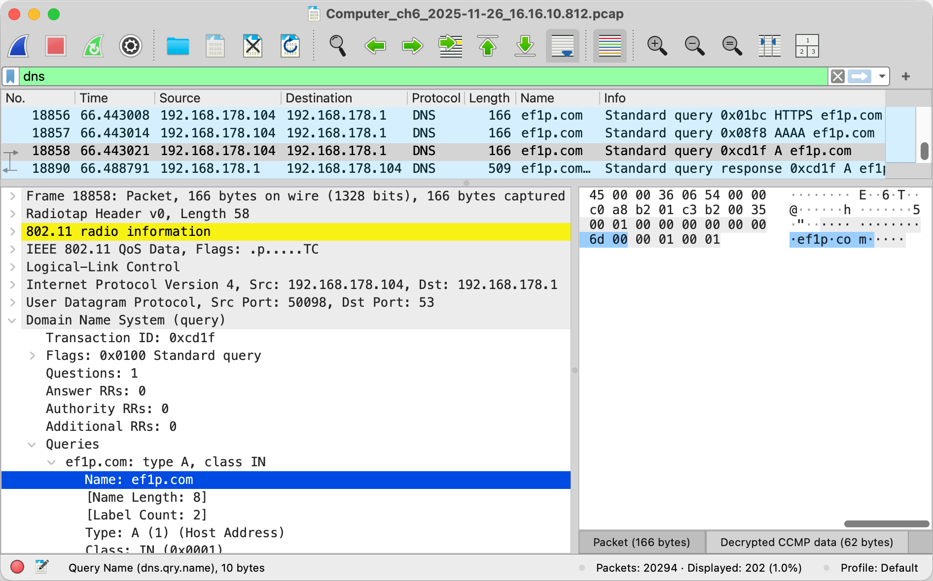
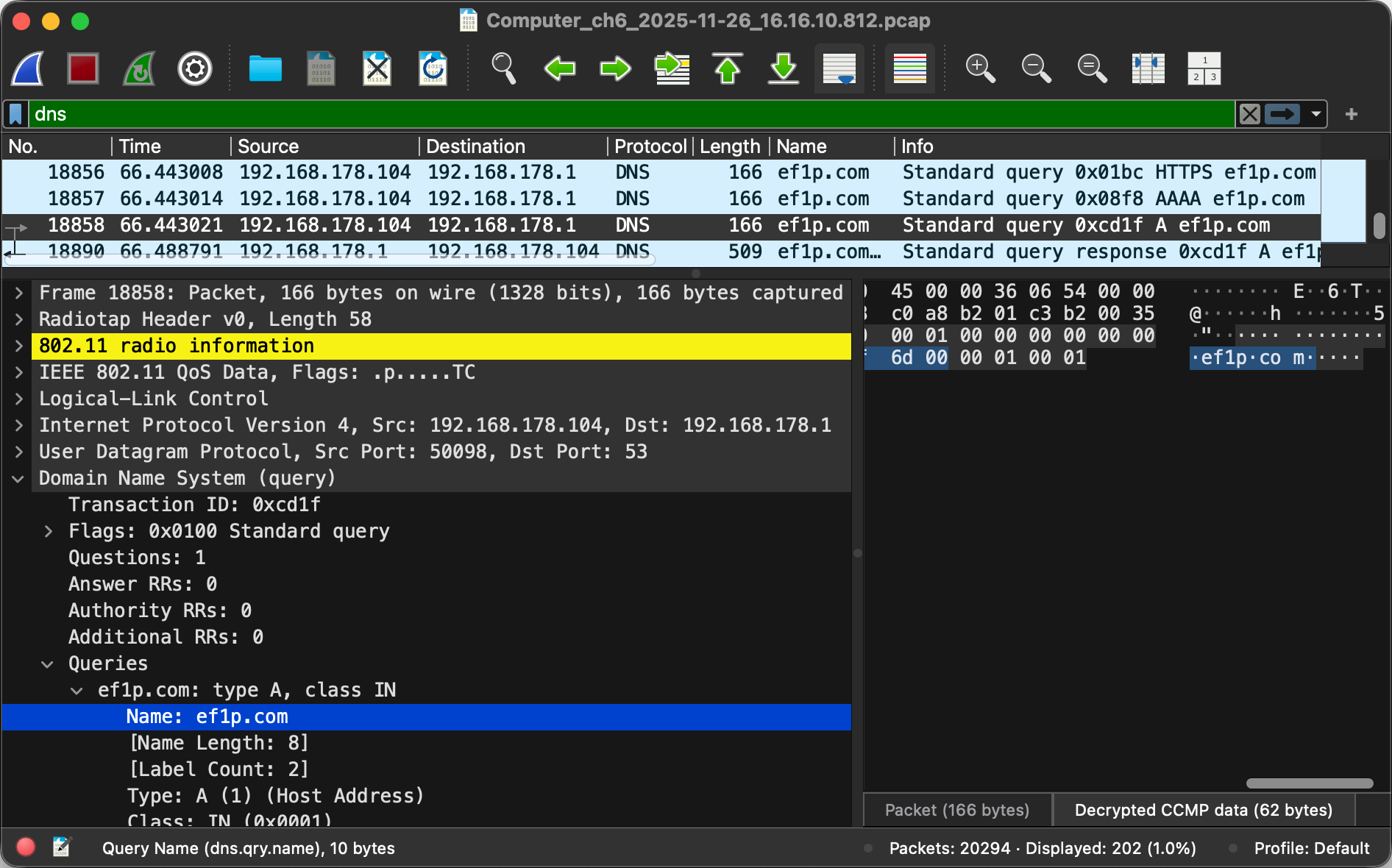
192.168.178.1. As you can see on the line where it says User Datagram Protocol in the lower left quadrant, the selected query was sent to the port 53. In the lower right quadrant, you can see where the query name, which I selected on the left, appears in the sequence of sent bytes. I added the “Name” column in the table with the filtered packets by right-clicking on the (selected) “Name: ef1p.com” field in the lower left quadrant and then choosing “Apply as Column”. The router sent the responses to the three queries in a single 802.11n frame using MAC service data unit (MSDU) aggregation, which is why the length of the packet on the last line is three times bigger.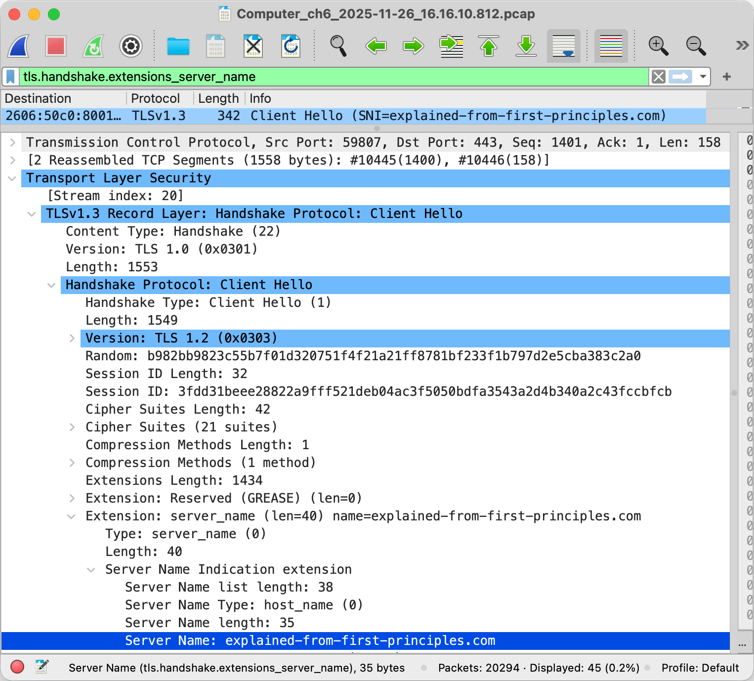
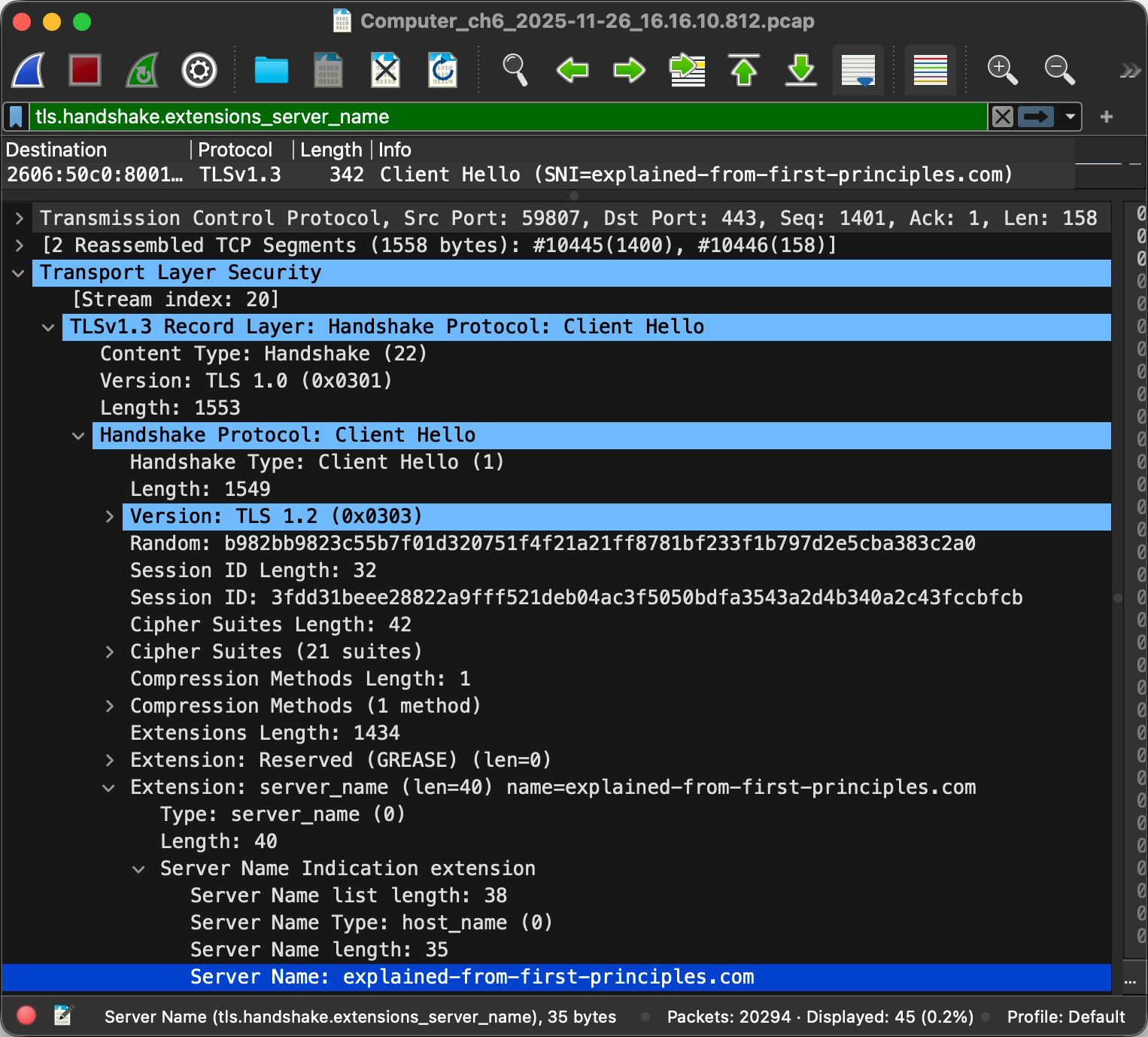
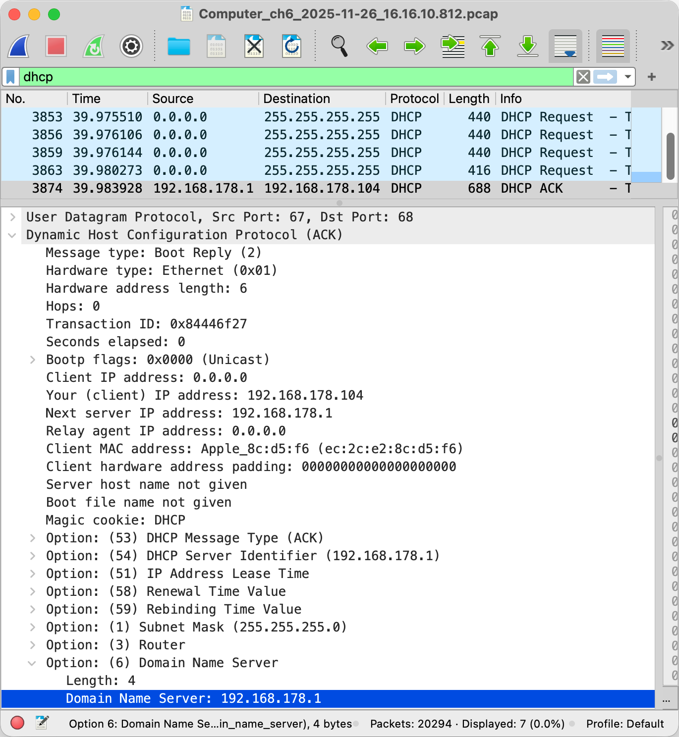
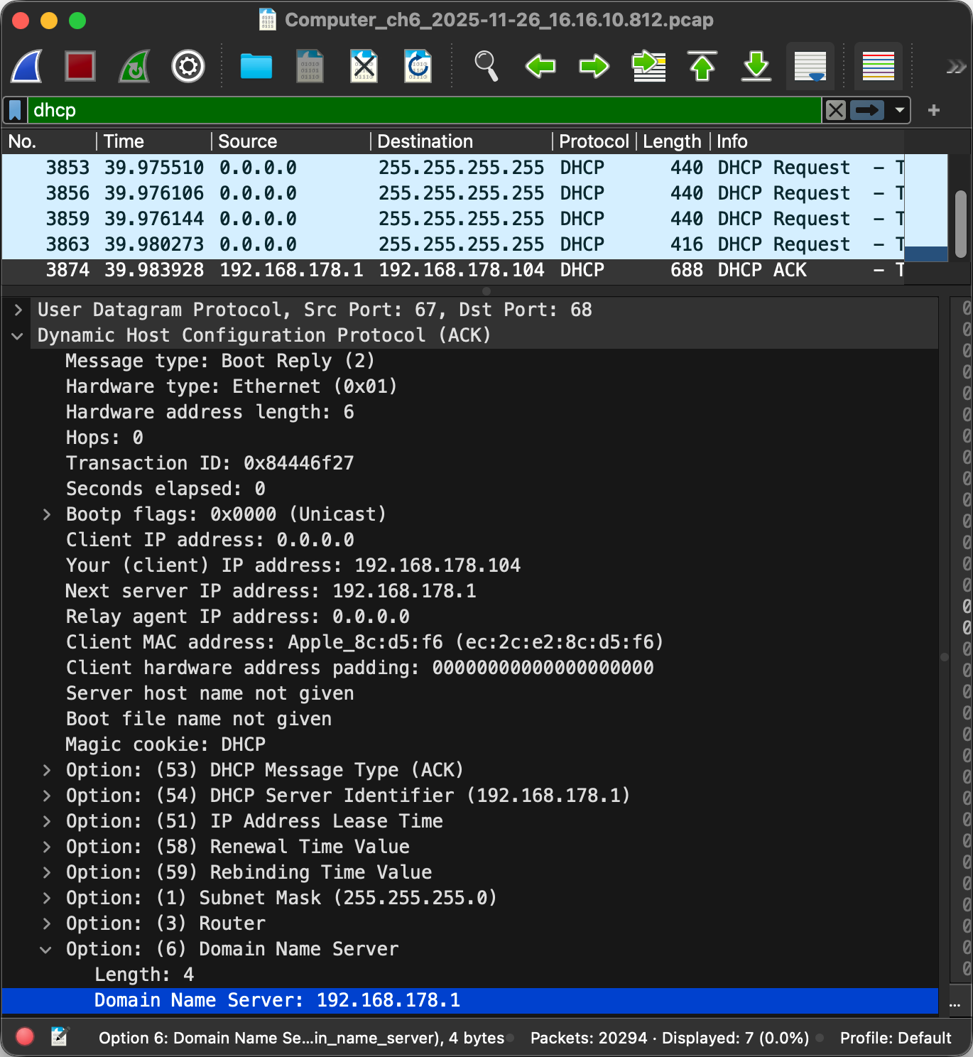
0.0.0.0 as the source for DHCP queries and sends them to the broadcast address 255.255.255.255, which is limited to the local network. The router with the IP address 192.168.178.1 assigned the IP address 192.168.178.104 to my iPad in the selected packet. (On the link layer, each device is addressed with its MAC address.) As you can see in the screenshot, the router also told my iPad in the option 6 of DHCP to send all DNS queries to the router.Application layer
Everything we’ve covered so far serves a single purpose: to accomplish things we humans are interested in. This is done with protocols on the application layer. Examples of application-layer protocols are the HyperText Transfer Protocol (HTTP) as the foundation of the World Wide Web (WWW), the Simple Mail Transfer Protocol (SMTP) for delivering email, the Internet Message Access Protocol (IMAP) for retrieving email, and the File Transfer Protocol (FTP) for, as you can probably guess, transferring files. What all of these protocols have in common is that they all use a text-based format, that they all run over TCP, and that they all have a secure variant running over TLS, namely HTTPS, SMTPS, IMAPS, and FTPS. This is the beauty of modularization: Application-layer protocols can reuse the same protocols below, while the protocols below don’t need to know anything about the protocols above.
Text encoding
Similar to numbers, human language is also encoded with symbols. By assigning meaning to specific combinations of symbols, which we call words, we can encode a large vocabulary with relatively few symbols. In computing, the symbols which make up a text are called characters. English texts consist of letters, digits, punctuation marks, and control characters. Control characters are used to structure texts without being printed themselves. So-called whitespace characters, such as space, tab, and newline, fall in this category. Other examples of control characters are backspace, escape, the end-of-transmission character, and the null character to indicate the end of a string. (A string is just a sequence of characters in memory.)
In order to uniquely identify them, a so-called code point is assigned to each character. A code point is just a number, which itself needs to be encoded in order to store or transmit text. In order to understand each other, two or more parties need to agree on a common character encoding. After the Morse code for telegraphs, the American Standard Code for Information Interchange (ASCII), which was developed in the 1960s, became the first widely adopted character encoding for computers. Based on the English alphabet, ASCII specifies 128 characters and how they are encoded as seven-bit integers. It is basically just a table mapping characters to their code points and vice versa. Since it’s easier to reserve a whole byte for each character, the eighth bit made it possible to extend ASCII with 128 additional characters. Many companies used this for proprietary extensions, before the International Organization for Standardization (ISO) published ISO 8859 in 1987, which standardized character sets for Western European languages, Eastern European languages, and others.
The character encodings defined by ISO 8859 have the problem that they are not compatible with each other. Since character encodings are typically used for whole documents including websites and not just for parts of them, you cannot use characters from different sets in the same document. Additionally, each document has to be accompanied with the used character set as part of its metadata because none of the encodings will ever be in a position to supersede them all as a widely accepted default encoding. Unicode, which is maintained by the California-based Unicode Consortium, unifies different character sets by providing a unique code point for every imaginable character. Unicode specifies different encodings for these code points, which are known as Unicode Transformation Formats (UTF). The most popular ones are UTF-8, which uses one to four bytes for each code point and maximizes compatibility with ASCII, and UTF-16, which uses one or two 16-bit units per code point.
Text-based protocols
A communication protocol has to specify
how text and numbers in messages are encoded
or at least how the recipient is informed about the used encoding.
As mentioned above,
many application-layer protocols are
text-based,
which means that the transmitted messages can be meaningfully displayed in a text editor.
This is in contrast to binary protocols,
whose messages are difficult to read for humans without specialized analysis software.
As we just learned, text is also encoded with binary numbers,
and text editors can be considered as specialized software.
The real difference between the two categories of protocols is
that text-based protocols delimit different pieces of information
with a certain character, such as a newline or a colon, at that position,
whereas binary protocols often define specific lengths in bytes for each
field
or prefix a field with its length in bytes.
The advantage of binary protocols is
that they can directly incorporate arbitrary data,
whereas the data in text-based protocols needs to be
escaped
in order to ensure that the delimiting character does not occur within a field.
If, for example, different header fields are separated by a newline,
then none of the header fields may contain a newline character.
If they do, the newline character needs to be replaced
with the appropriate escape sequence
as defined by the protocol.
A common escape sequence for a newline character is \n.
Alternatively, the whole data could be re-encoded with a certain set of characters.
This is required when arbitrary data needs to be encoded
where only text is permitted or reliably supported.
This is the case for email attachments
because email originally supported only 7-bit ASCII.
If you attach a picture to an email, for example,
the picture is split into chunks of 6 bits,
and each chunk is encoded with one of 64 characters.
This encoding is called Base64,
and it needs to be reverted by the recipient
in order to display the picture.
Base64 uses the characters A – Z, a – z, 0 – 9, +, and /
(26 + 26 + 10 + 2 = 64).
Because binary protocols require no such transformation
and often omit field labels
or replace them with numeric tags,
they are more compact and efficient than text-based protocols.
HyperText Transfer Protocol (HTTP)
In order for you to read this article,
your browser fetched this page from a
web server via HTTP over TLS,
which is known as HTTPS.
Given the popularity of the Web,
HTTP is one of the most widely used application-layer protocols.
If we ignore newer versions of the protocol and rarely used features,
HTTP is a fairly simple protocol and thus an excellent first example.
HTTP works according to the client-server model:
The client sends a request, and the server sends back a response.
The first line of the request starts with the
request method,
which specifies whether the request is about
retrieving (GET) or submitting (POST) data.
The request method is followed by
the resource to retrieve or submit to
and the protocol version.
The first line of the response includes the
status code,
which indicates whether the request was successful
and, if not, what went wrong.
While the first line is different,
both HTTP requests and responses continue with
header fields
(formatted as name: value on separate lines),
an empty line,
and an optional message body.
If you request a file,
the body of the request is usually empty,
whereas the body of the response contains the file
(assuming that the request was successful).
If, on the other hand, you submit data,
such as your username and password in a login form,
the request contains this data in its body,
whereas the body of the response could be empty,
for example, when your browser is being redirected to a different page.
We have encountered the concept of header and payload several times already,
and HTTP follows the same logic.
Let’s look at a slightly modified example from
Wikipedia:
GET /index.html HTTP/1.0
Host: www.example.com
/index.html from the host www.example.com.
Please note that the request is terminated by an empty line and has no message body.
The only mandatory request header field is Host.
It is required to let the server know
from which website to serve the requested resource
in case the same server hosts several websites.
As you learned above,
only one process can bind to a specific port on the same machine,
thus this header field is the only way for a server
to tell the requests to different websites apart.
(Strictly speaking, it’s one process
per port number and IP address.
So if the server has several network interfaces,
the requests on each interface could be handled by a different process.)
The default port is 80 for HTTP and 443 for HTTPS.
If you want to request a website on a different port,
you would specify this after the host name in the
URL.
For example, if you run a web server locally on port 4000,
you would access it at http://localhost:4000/ in your browser.
Let’s look at the response:
HTTP/1.0 200 OK
Date: Mon, 23 May 2005 22:38:34 GMT
Content-Type: text/html; charset=UTF-8
Content-Length: 155
Last-Modified: Wed, 08 Jan 2003 23:11:55 GMT
Server: Apache/1.3.3.7 (Unix) (Red-Hat/Linux)

<html>
  <head>
    <title>An example page</title>
  </head>
  <body>
    <p>Hello, World! This is a very simple HTML document.</p>
  </body>
</html>
As indicated by the Content-Type header field,
the response is an HTML document.
HTML stands for HyperText Markup Language
and is the document format of the Web.
The browser parses the HTML document
and displays it as a website.
<p> stands for a paragraph, which is then closed by </p>.
The other so-called tags
in the example above should be self-explanatory.
Usually, a website references other files from its HTML,
such as styles,
scripts,
and images.
These files can be hosted on the same or a different server.
The browser fetches them via separate HTTP requests.
The body of the response is not limited to text-based formats,
any files can be transferred via HTTP.
Thanks to the Content-Length header field,
binary files don’t need to be escaped.
Every modern browser includes powerful
developer tools,
with which you can inspect the requests it made:

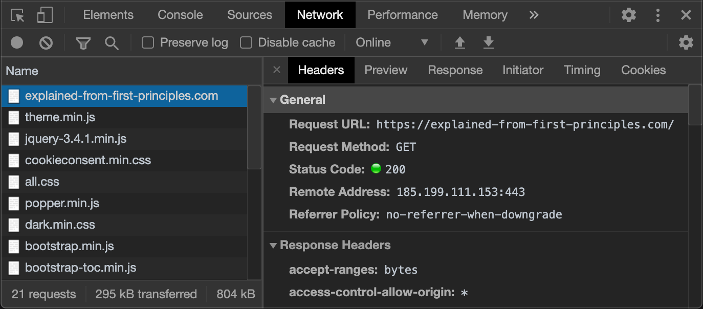
If you are familiar with the command-line interface
of your operating system,
you can write such HTTP requests yourself.
On macOS,
the default program providing such a command-line interface
is Terminal,
located in the /Applications/Utilities folder.
With the networking utility nc,
you can establish a TCP connection to the designated server.
If the website is provided via HTTPS,
you can use OpenSSL
to establish a TLS connection to the designated server.
The following tool generates what you have to enter in your command-line interface
based on the provided Web address:
Domain Name System (DNS)
Name registration
The hierarchical numbers used in network addresses
are great for machines to route packets
but difficult for humans to remember.
The Domain Name System (DNS)
as specified in RFC 1034 and RFC 1035
solves this problem by providing a hierarchical
namespace
of easily memorizable domain names
and a protocol to access public information associated with such names.
A domain name consists of a sequence of labels separated by a dot.
Similar to how the Internet
is more than just a protocol as it also governs the allocation of IP addresses,
the Domain Name System is more than just an application-layer protocol
as it also governs the allocation of domain names,
thereby ensuring that each domain name is unique.
At the root of this system is again the
Internet Corporation for Assigned Names and Numbers (ICANN),
which approves the top-level domains (TLD)
and accredits the registry operators,
which manage the registration of names within their domain.
As an organization or individual,
you register your domains at a so-called
domain name registrar,
which has to be accredited by the registry operators
of all the top-level domains under which it allows its customer to register a domain name.
This has the advantage that you as a registrant have to interact with only a single company
even if you register various domain names under different top-level domains.
Let’s look at an example: I’m the registrant of ef1p.com.
The top-level domain of this domain name is com.
The registry operator for .com is Verisign.
The domain name registrar I have chosen to register my domains is Infomaniak.
I pay them around 18 USD every year just so that I can keep this domain.
In order to avoid ambiguity,
a fully qualified domain name (FQDN)
is sometimes written with a trailing dot, such as ef1p.com..
Otherwise, the label might just refer to a subdomain.
Don’t let this confuse you in the DNS lookup tool below.
Distributed database
From a technical point of view, DNS acts as a distributed database, which stores the information associated with domain names on numerous machines distributed all over the Internet. These machines are called name servers, and each entry they store is called a resource record (RR). While some name servers provide the authoritative answer to queries regarding the domain names for which they are responsible, others simply store these answers for a limited period of time. Such temporary storage is known as caching, and it allows other devices in the same network to look up the information faster. Caching is also important to distribute the load more evenly among name servers, which improves the scalability of the Domain Name System. Each record specifies how long it can be cached, which limits how outdated the answer to a query can be. This expiration period is called time to live (TTL), and a common value for this is one hour. This means that if you change a DNS record with such a TTL value, you have to wait for up to one hour until the stale entries have been discarded everywhere.
IP address lookups
The most common use case of DNS is to resolve a domain name to an IP address. Every time a client connects to a server identified by a domain name, it first has to query a name server to obtain the IP address of the server because the network layer has no notion of domain names. This is similar to how you have to look up the phone number of a person before you can call that person. In this sense, DNS can be compared to a telephone book; but, rather than looking up the phone number of persons, you look up the IP address of computers on the Internet. Another difference is that each domain name is unique, which cannot be said about the names of humans. A domain name can resolve to several IP addresses, which distributes requests among several servers and allows clients to connect to a different server if they cannot reach one of them. This indirection of first having to look up the IP address of the server you want to connect to also has the advantage that a server can be replaced without having to notify its users about the new address.
Transport protocol
DNS specifies a binary encoding for requests and responses. By default, DNS uses the User Datagram Protocol (UDP) in order to avoid the additional round trips required by the Transmission Control Protocol (TCP) for the connection setup. If the request or the response packet is lost, the client simply queries again after the configured timeout. If not all queried resource records fit into a single UDP packet (see the maximum transmission unit), the DNS server indicates this in its response. In such a case, the client should discard the UDP response and send the same query over TCP again. DNS is served on port 53 for UDP and TCP.
Resource record types
There are other types of resource records besides the one which resolves a domain name to an IPv4 address:
| Acronym | Name | Value | Example |
|---|---|---|---|
A |
IPv4 address record | A single IPv4 address. | ↗ |
AAAA |
IPv6 address record | A single IPv6 address. | ↗ |
ANY |
Any record type query | Return all record types of the queried domain. | ↗ |
CAA |
CA authorization record | The CA authorized to issue certificates for this domain. Only checked by CAs before issuing a certificate. |
↗ |
CNAME |
Canonical name record | Another domain name to continue the lookup with. | ↗ |
MX |
Mail exchange record | The server to deliver the mail for the queried domain to. | ↗ |
NS |
Name server record | The authoritative name server of the queried domain. | ↗ |
OPENPGPKEY |
OpenPGP key | The local part of the user’s email address is hashed. | ↗ |
PTR |
Pointer record | Another domain name without continuing the lookup. Primarily used for implementing reverse DNS lookups. |
↗ ↗ |
SMIMEA |
S/MIME certificate | The local part of the user’s email address is hashed. | ↗ |
SOA |
Start of authority record | Administrative information for secondary name servers. | ↗ |
SRV |
Service record | The port number and domain name of the queried service. | ↗ |
SSHFP |
SSH fingerprint | The hash of the server’s SSH key for initial authentication. | ↗ |
TLSA |
Server certificate | See DNS-Based Authentication of Named Entities (DANE). | ↗ |
TXT |
Text record | Arbitrary text used in place of introducing a new record type. | ↗ |
DNS lookup tool
We will encounter some of these record types in future articles on this blog. For now, I want to give you the opportunity to play around with the actual DNS. I use an API by Google to query what you enter. Try it with any domain name you are interested in. If you hover with your mouse over the data, you get additional explanations and options, such as doing a reverse lookup of an IPv4 or IPv6 address. The DNSSEC option and the record types which are not in the above table will be introduced here and here. If you want to play around with the tools in this article without scrolling, I also published them separately on this page.
Domain Name System Security Extensions (DNSSEC)
DNS security issues
The problem with plain old DNS is that the answer to a query cannot be trusted. While non-authoritative name servers that cache and relay answers for others are great for scalability, they are really bad for security as they can reply with fake answers, thereby poisoning the cache of DNS resolvers. Additionally, an attacker who can modify your network traffic can also replace the actual response from a name server with a malicious one because neither UDP nor IP authenticates the transmitted data. To make things even worse, an attacker might not even have to modify your network traffic. As long as the attacker sees your DNS query by being on the same network, they can simply respond faster than the queried name server. Since UDP is a connectionless protocol without a handshake, the source IP address of the response can easily be spoofed so that it seems as if the response was indeed sent from the queried name server. If the attacker does not see the query because they are on a non-involved network, such a race attack becomes much harder as the attacker has to guess the correct timing of the response, the correct DNS query ID used to match answers to questions, as well as the correct source port from which the query was sent. For this reason, DNS queries should always be sent from a random source port, and also NAT routers should choose external ports unpredictably. Since DNS is often used to determine the destination address of requests, a successful attack on the DNS resolution of your computer allows the attacker to redirect all your Internet traffic through servers that they control. The only thing that can limit the damage they can do is TLS with valid public-key certificates or another protocol with similar security properties on the application layer. This also requires that the user does not simply dismiss warnings about invalid certificates. Luckily, such warnings are quite intimidating in most browsers by now and can no longer be dismissed with a single click. If you don’t know what I’m talking about, visit this page in order to get such a warning. There is no risk in visiting this page as long as you abort and don’t modify your security settings.
Authenticity without confidentiality
The Domain Name System Security Extensions (DNSSEC) solve these DNS security issues by authenticating resource records. DNSSEC doesn’t provide confidentiality, though. You would have to use another protocol for that. For most readers, it’s enough to know that the integrity of DNS can be protected. The rest of this box dives fairly deep into how DNSSEC works according to RFC 4033 (overview and considerations), RFC 4034 (new types of resource records), and RFC 4035 (protocol modifications).
Administrative zones
Before we can discuss these extensions,
we first need to understand
that the Domain Name System is split into administrative zones,
each of which is managed by a single entity.
Each such entity runs name servers (or lets a company run them on its behalf),
which return the authoritative answers for the domains in its zone.
DNS has a single and thus centralized root zone,
which is managed by the Internet Assigned Numbers Authority (IANA),
a subsidiary of the Internet Corporation for Assigned Names and Numbers (ICANN),
but operated by Verisign.
The root domain is denoted by the empty label,
but it is usually written and queried as a single period: ..
If you query a root name server
for a domain such as ef1p.com.
(written with a trailing dot because com is a subdomain of the root domain with the empty label),
it will answer that com belongs to a different DNS zone
and provide you with the addresses of the authoritative name servers of that zone.
If you query one of those name servers for ef1p.com.,
it will tell you again that other name servers are responsible for this domain.
You can query all these name servers with the tool at the end of the previous box:
the root name servers,
the .com name servers,
and the ef1p.com name servers.
Somewhat confusingly, the name servers are listed with a domain name rather than an IP address.
In order to avoid the circular dependency
that you already need to have used DNS in order to use DNS,
DNS clients have to be delivered not only with the domain names of the root name servers but also with their IP addresses.
This is usually accomplished with a file like this.
As long as they can reach one of the root name servers,
it will tell them the IP address of any name server it refers them to as well.
This is accomplished with so-called glue records,
which are address resource records for name servers in a subzone returned by the name server of the superzone.
I cannot demonstrate this with the above tool
because Google does all the recursive resolution for us.
If you are familiar with a command-line interface,
you can use the dig command to check this:
dig net @a.root-servers.net. returns in the authority section of the DNS answer
that the name server for net. is a.gtld-servers.net. (among others)
and in the additional section of the DNS answer
that the IPv4 address of a.gtld-servers.net. is 192.5.6.30.
(The authority section indicates the
authoritative name servers
of the queried domain or its canonical name.
In the additional section,
a name server can add records
that are related to the query
but which the client didn’t yet ask for.)
While for a domain name such as ef1p.com.
each subdomain starts its own zone as we have just seen,
I would declare any further subdomains, such as www.ef1p.com.,
in the same zone as ef1p.com..
Since I’m the administrator of my zone,
I can do this without involving any party
other than infomaniak.com,
which operates the name servers on my behalf,
thanks to the hierarchical and distributed nature of DNS.
Single trust anchor
Coming back to DNSSEC after this little detour,
the core idea is that each zone signs its records
and provides these signatures in newly created records.
Each administrative zone uses its own cryptographic keys for this,
but the zone above in the hierarchy lists and signs the public keys of its subzones.
This allows you to verify the public keys and resource records of all DNSSEC-enabled zones
as long as you know the public key of the root zone.
This is similar to the public-key infrastructure behind TLS,
where root certification authorities delegate their authority to intermediate certification authorities
by signing their public key.
There is a crucial difference, though.
In the case of TLS, everyone needs to trust every single certification authority
since any certification authority can issue a certificate for any domain.
With DNSSEC, you need to trust only the administrators of the zones above you.
For this blog, that’s the root zone and the com. zone.
A zone like attacker.example.org. cannot authorize a different DNSSEC key for ef1p.com..
In computer security, requiring less trust is always better.
While DNSSEC fails spectacularly if the root key is compromised,
TLS fails if the key of any certification authority is compromised.
Having a single point of failure
is preferable to having many independent points of failure.
There have been attempts to address this issue for TLS,
but, unfortunately, they weren’t widely adopted.
Let’s have a look at some technical aspects of DNSSEC next.
DNSSEC resource records
DNSSEC introduced the following DNS record types:
| Acronym | Name | Value | |
|---|---|---|---|
DNSKEY |
DNS public key record | The public key used to sign the resource records of the queried domain. | ↗ |
DS |
Delegation signer record | The hash of the key-signing key (KSK) used in the delegated DNS zone. | ↗ |
RRSIG |
Resource record signature | A digital signature on the queried set of resource records. | ↗ |
NSEC |
Next secure record | The next existing subdomain used for authenticated denial of existence. | ↗ |
NSEC3 |
NSEC version 3 |
A salted hash of the next existing subdomain to prevent zone walking. | ↗ |
NSEC3PARAM |
NSEC3 parameters |
Used by authoritative name servers to generate the NSEC3 records. |
↗ |
CDS |
Child copy of DS |
Used by the child zone to publish the desired DS record in the parent zone. |
↗ |
CDNSKEY |
Child copy of DNSKEY |
Used by the child zone so that the parent zone can compute the DS record. |
↗ |
Key-signing keys and zone-signing keys
Although DNSSEC validation treats all keys equally,
RFC 4033
distinguishes between key-signing keys (KSKs)
and zone-signing keys (ZSKs).
A zone lists both types of keys with DNSKEY records.
The parent zone lists the cryptographic hash
of the key-signing key in a DS record.
(A hash is the result of a one-way function,
which maps inputs of arbitrary size to outputs of a fixed size and is infeasible to invert.)
By using only the hash of a key instead of the key itself,
the parent zone has to store less data because the hash is shorter.
And of course, we’re talking only about public keys here.
The key-signing key is then used to sign one or more zone-signing keys.
The signature, which covers all DNSKEY records,
is published in an RRSIG record with the same domain name.
The zone-signing keys are then used to sign all other records of the zone.
The advantage of this distinction between key-signing keys and zone-signing keys
is that the latter can have a shorter lifetime
and be replaced more frequently because,
unlike in the case of key-signing keys,
the parent zone is not involved.
The algorithms that can be used to sign records are listed
on Wikipedia
and, more authoritatively, by IANA.
The supported hash algorithms for DS records are listed here.
Key-signing ceremonies
As mentioned above,
the key-signing key of the root zone acts as the trust anchor for DNSSEC.
Its hash is published on the website of IANA
together with a scan of handwritten signatures by trusted community representatives,
attesting the output of the used hardware security module (HSM).
You can inspect the root public key with the above tool
or by entering dig . dnskey +dnssec into your command-line interface.
(The key-signing key is in the record which starts with 257.
The other record, starting with 256, contains the zone-signing key.)
All DNSSEC-aware DNS resolvers are delivered with a copy of this public key
in order to be able to validate resource records recursively.
The corresponding private key is stored in two secure facilities,
which safeguard the root key-signing key with geographical redundancy.
One of them is located on the US West Coast in El Segundo, California,
the other one on the US East Coast in Culpeper, Virginia.
All ceremonies involving this private key
are publicly documented
in order to increase trust in the root key of DNSSEC.
For example, you can download the log files
as well as camera footage from different angles from a recent ceremony.
I can also recommend you to read this first-hand account.
Offline signing
For performance and security reasons, DNSSEC has been designed so that the resource records in a zone can be signed before being served by a name server. This allows the records to be signed on an air-gapped computer, such as an HSM, which never needs to be connected to the Internet and is thus never exposed to network-based attacks. As far as performance is concerned, name servers don’t have to perform cryptographic operations for each request, which means that fewer machines can serve more requests. By not requiring access to the private key, name servers including the root servers can be located all over the world without potential for abuse by local governments. While China, for example, can (and does) inject forged DNS responses in order to censor content on its network, this practice is prevented or at least consistently detected when DNSSEC is used. In other words, you have to trust only the administrator of a zone and not the operator of an authoritative name server. As mentioned just a few paragraphs earlier, requiring less trust is always better in computer security.
Resulting design complexity
Allowing the signatures to be computed in advance makes DNSSEC more complicated in several regards:
- Replay attacks: Even if an attacker cannot forge a valid response,
they can replace the response to a new request with the response from an earlier request
if they can intercept the traffic on the victim’s network.
This is known as a replay attack
and is usually prevented by including a random number used only once
in the request, which then also has to be included in the authenticated response.
However, due to the above design decision,
DNSSEC signatures cannot depend on fresh data from the client.
Since the potentially precomputed signatures stay the same for many requests
and DNSSEC doesn’t authenticate anything else in the response,
such as the DNS packet itself including its header,
an attacker can replay outdated DNS records including their DNSSEC signatures.
In order to limit the period during which DNS records can be replayed,
RRSIGrecords include an expiration date, after which the signature may no longer be used to authenticate the signed resource records. Suitable validity periods for DNSSEC signatures are discussed in section 4.4.2 of RFC 6781.
- Denial of existence: How can you be sure that a domain name doesn’t exist
or doesn’t have the queried record type
without requiring the authoritative name server to sign such a statement on the fly?
Since each label of a domain name (the part between two dots) can be up to 63 characters long,
a domain can have more direct subdomains than there are
atoms in the observable universe.
(The limit of 63 characters is imposed by RFC 1035
because the DNS protocol encodes the length of a label with a 6-bit number.)
This makes it impossible to generate and sign negative responses for all nonexistent subdomains in advance.
A generic negative response, which doesn’t depend on the queried domain name, doesn’t work
because an attacker could replay such a response even when the queried domain does exist.
Instead of mentioning the nonexistent domain in the response,
DNSSEC achieves authenticated denial of existence
by returning that no subdomain exists in a given range,
which includes the queried domain.
Since all domains in a zone are known to the administrator of that zone,
the gaps between the subdomains can be determined and signed in advance.
For example, if you query the nonexistent domainnonexistent.ef1p.com., you get anNSECrecord in the authority section of the response, which says that the next domain name in the zone afterhello.ef1p.com.iswww.ef1p.com., and anRRSIGrecord, which signs theNSECrecord. Sincenonexistent.ef1p.com.comes afterhello.ef1p.com.and beforewww.ef1p.com.in the alphabetically sorted list of subdomains in that zone, we now know for sure that this domain does not exist. The base domain of the zone, which isef1p.com.in our example, is not just at the beginning of this list but also at the end. If you click on the magnifying glass afterwww.ef1p.com.in the data column of theNSECrecord in order to query theNSECrecord ofwww.ef1p.com., you see that the next domain afterwww.ef1p.com.isef1p.com.. In other words, the list of subdomains wraps around for the purpose of determining the gaps to sign.
EachNSECrecord also specifies the types of records that the domain to which it belongs has. If you query, for example, theMXrecord ofhello.ef1p.com., you get theNSECrecord of that domain instead. SinceMXis not listed in thisNSECrecord, you can be certain that no such record exists. While an attacker might still be able to drop the response to your DNS query,NSECrecords prevent them from lying about the existence of a domain name or record type. In particular, they cannot strip DNSSEC information from a response because a resolver can check whether a zone has DNSSEC enabled by querying theDSrecord in the parent zone. Since the resolver knows that the root zone has DNSSEC enabled, the attacker would have to be able to deny the existence of aDSrecord in an authenticated zone, which they cannot do thanks to the mechanism described in this paragraph. In practice, your zone can have DNSSEC enabled only if all the zones above it have DNSSEC enabled.
- Zone walking:
NSECrecords create a new problem, though. By querying theNSECrecord of the respective subsequent domain, you can enumerate all the domains in a zone, which is known as walking the zone. While all the information in the Domain Name System is public in the sense that it can be requested by anyone because the sender of a query is never authenticated, you previously had to guess the names of subdomains. Since I couldn’t find a tool to walk a DNS zone online (the closest one I could find works completely differently), I built one for you, using the same Google API as before:Unfortunately, not many domains have DNSSEC records, and most of them which do use
NSEC3rather thanNSEC. It’s thus not easy to find domains to feed into this tool. Besides the root zone, which is walkable, some top-level domains (TLD) also useNSECrecords for authenticated denial of existence, which means that one can list all domains registered under such a TLD. Among those are country-code top-level domains such as .br (Brazil), .kg (Kyrgyzstan), .lk (Sri Lanka), .lr (Liberia), .pr (Puerto Rico), and .tn (Tunisia), as well as generic top-level domains such as .audio, .auto, .game, .hosting, .lol, and .pics.
For security and privacy reasons, many organizations prefer not to expose the content of their zone so easily. This problem was first addressed by RFC 4470, which suggested generating and signing minimally coveringNSECrecords for nonexistent domains on the fly, and later by RFC 5155, which introduced the new record typeNSEC3. As the former proposal abandons offline signing, thereby sacrificing security for better privacy, we’ll focus on the latter proposal in this bullet point.
Instead of determining the gaps between domain names directly, all domain names in a zone are hashed in the case ofNSEC3. These hashes are then sorted, and anNSEC3record is created for each gap in this list. If a DNS resolver queries a domain name that doesn’t exist, the name server responds with theNSEC3record whose range covers the hash of the queried domain. Similar toNSECrecords,NSEC3records also list the record types that exist for the domain name which hashes to the start of the range. Thus, if the queried domain name exists but the queried record type doesn’t, a resolver can verify such a negative response by checking that the hash of the queried domain matches the start value of the receivedNSEC3record. AnNSEC3record also indicates which hash function is used, how many times the hash function is applied to a domain name, and optionally a random value, which is mixed into the hash function in order to defend against pre-computed hash attacks. While an attacker can try to brute-force the names of subdomains based on the hashes it received inNSEC3records, such a random value restricts the attack to one zone at a time. The computational effort of such a targeted attack can be increased by increasing the number of times the hash function is applied. The difference to just querying guessed subdomain names is that the search for the preimage of a hash can be done without interacting with the authoritative name server.
Besides protecting the domain names with a one-way function,NSEC3also allows to skip the names of unsigned subzones when determining the gaps to sign by setting the opt-out flag. By skipping all subzones that don’t deploy DNSSEC, the size of a zone can be reduced as fewerNSEC3records are required. While easily guessable subdomains, such aswwwormail, have to be considered public anyway,NSEC3protects the resource records of subdomains with more random names reasonably well.
Please note that the DNS query still has to include the actual domain name and not its hash. By just learning the hash of a subdomain, you don’t yet know the domain name to query. However, it’s still relatively easy to figure out the overall number of domain names in a zone by probing the name server with names that hash to a range for which you haven’t seen anNSEC3record yet. Hash functions make only the task of finding an input that hashes to a specific output hard, but if the output just has to land in a certain range, then the bigger the range, the easier the problem. Even if you introduce additional dummyNSEC3records, you still leak an upper limit of domain names in the zone.
- Compact Denial of Existence: Since publishing this article,
online signing (i.e. computing RRSIG signatures on demand instead of in advance) has become more popular.
In September 2025, RFC 9824 has been published,
which suggests to respond to a query for a nonexistent domain
by claiming that the domain name exists but that it has no resource records of the queried type.
For this purpose, the RFC introduces a new record type
NXNAME, which can be listed inNSECrecords to signal that the queried domain name does not exist. In the next domain name field of theNSECrecord, the queried domain name is prefixed with a label consisting of a single null octet, which is written as\000. You can see this when you query nonexistent.ietf.org. Zones which use this technique, such as ietf.org, cannot be walked.
- Wildcard expansion: Last but not least,
wildcard records
make DNSSEC even more complicated.
The idea of a wildcard record is
that it is returned
whenever the queried domain name doesn’t exist in the zone.
For example, if an ordinary record is declared at
mail.example.com.and a wildcard record is declared at*.example.com., with*being the wildcard character, a query formail.example.com.will return the former record, and a query foranything-else.example.com.will return the latter. The wildcard can be used only as the leftmost DNS label and cannot be combined with other characters on that level. Thus, neithermail.*.example.com.normail*.example.com.is a wildcard record. For a wildcard record to match, the domain name may not exist on the level of the wildcard. The above wildcard record matchesanything.else.example.com.becauseelse.example.com.doesn’t exist, but it doesn’t matchanything.mail.example.com.becausemail.example.com.exists. Whether a wildcard name matches is determined independently from the queried record type. For example, ifmail.example.com.has only anMXrecord while*.example.comhas anArecord, then queryingmail.example.com.for anArecord returns no data. However, not all implementations adhere to these rules. Without DNSSEC (or when Compact Denial of Existence is being used to generate a response for the queried domain name on the fly), DNS resolvers don’t learn whether an answer has been synthesized from a wildcard record or whether the returned record exists as such in the zone.
Since signatures cannot be precomputed for all possible matches,RRSIGrecords indicate the number of labels in the domain name to which they belong, without counting the empty label for the root and the potential wildcard label. This allows a validator to reconstruct the original name, which is covered in the signature and thus required to verify the signature. For example, when querying the IPv4 address ofanything.else.example.com., the returnedArecord is accompanied by anRRSIGrecord with a label count of 2. This tells the validator to verify the signature for*.example.com.. If the label count was 3, it would have been*.else.example.com..
Equally importantly, we need to ensure that this wildcardRRSIGrecord cannot be replayed for domain names that do exist, such asmail.example.com.in our example. For this reason, DNSSEC mandates that wildcardRRSIGrecords are valid only if anNSECor anNSEC3record proves that the queried domain name doesn’t exist. This means that the response toanything.else.example.com.includes not just anAand anRRSIGrecord but also anNSEC(3)record. The wildcard domain name is included as such in the list used to determine theNSEC(3)records. This is important to prove that a domain name doesn’t exist or that a synthesized domain name doesn’t have the queried record type. For example, the response foranything.mail.example.com.has to include anNSEC(3)record which proves thatanything.mail.example.com.doesn’t exist, anNSEC(3)record which proves thatmail.example.com.does exist, and anNSEC(3)record which proves that*.mail.example.com.doesn’t exist. If, on the other hand,anything-else.example.com.is queried for anMXrecord, the response has to include anNSEC(3)record which proves thatanything-else.example.com.doesn’t exist, and theNSEC(3)record at*.example.com., which proves that wildcard-expanded domain names don’t have records of this type. If some of theseNSEC(3)records are the same, the name server should include them and the correspondingRRSIGrecords only once in the authority section of the response. If this is still confusing, you find a longer explanation of wildcards in DNSSEC here.
- Amplification attacks:
By including relatively large
RRSIGrecords in its responses and by requiring up to threeNSEC(3)records for wildcard expansion, DNSSEC increases the size of DNS responses significantly. While the vast majority of DNSSEC responses still fit into a single UDP packet without having to fall back on TCP, an attacker can send a multiple of their own bandwidth to a victim’s computer by changing the source address of DNS requests with large responses to the victim’s IP address. This is known as a DNS amplification attack, which is a type of denial-of-service attack. DNS providers mitigate amplification attacks using techniques such as response rate limiting (RRL).
Varied adoption
Even though the Domain Name System is a core component of the Internet and should be secured accordingly, the deployment of DNSSEC varies a lot. While around a third of worldwide users indirectly use DNS resolvers which fully validate DNSSEC and more than half of all domains registered at several European country-code top-level domains, such as the Dutch (.nl), Czech (.cz), Norwegian (.no), Swedish (.se), and since 2025 also the Swiss (.ch) zone, use DNSSEC to authenticate their records, only around 4% of .com domains and around 5% of .net domains have DNSSEC enabled in 2025. When you play around with the above tool, you will note in particular that none of the big tech companies protect their DNS records with DNSSEC. As these companies dominate Internet traffic, around 96% of all DNS queries are for unsigned domain names. The reason for their reluctance to deploy DNSSEC seems to be operational risks (see this list of DNSSEC outages due to misconfigurations, which bring down a zone and its subzones with all their services) and overhead (key management with rollovers, larger responses, and potentially on-the-fly signing) with limited security benefits as most of their traffic is via HTTPS, whose communication is secured with TLS and public-key certificates. However, DNS supports more than just IP addresses of webservers, such as autoconfiguration of mail clients, indirect resolution of mail servers, and sender authentication of emails, among many other things, which DNSSEC secures as well.
Digest computation
IANA publishes the key-signing key of the root zone at https://data.iana.org/root-anchors/root-anchors.xml:
…
<KeyDigest id="Kmyv6jo" validFrom="2024-07-18T00:00:00+00:00">
  <KeyTag>38696</KeyTag>
  <Algorithm>8</Algorithm>
  <DigestType>2</DigestType>
  <Digest>683D2D0ACB8C9B712A1948B27F741219298D0A450D612C483AF444A4C0FB2B16</Digest>
  <PublicKey>AwEAAa96jeuknZlaeSrvyAJj6ZHv28hhOKkx3rLGXVaC6rXTsDc449/cidltpkyGwCJNnOAlFNKF2jBosZBU5eeHspaQWOmOElZsjICMQMC3aeHbGiShvZsx4wMYSjH8e7Vrhbu6irwCzVBApESjbUdpWWmEnhathWu1jo+siFUiRAAxm9qyJNg/wOZqqzL/dL/q8PkcRU5oUKEpUge71M3ej2/7CPqpdVwuMoTvoB+ZOT4YeGyxMvHmbrxlFzGOHOijtzN+u1TQNatX2XBuzZNQ1K+s2CXkPIZo7s6JgZyvaBevYtxPvYLw4z9mR7K2vaF18UYH9Z9GNUUeayffKC73PYc=</PublicKey>
  <Flags>257</Flags>
</KeyDigest>
…
You find the same digest in this PDF, which is covered with handwritten signatures by trusted community representatives. (Digest is just a synonym for hash.) In this section, I explain how the digest is computed. According to RFC 4034,
digest = digest_algorithm(DNSKEY owner name | DNSKEY RDATA);
DNSKEY RDATA = Flags | Protocol | Algorithm | Public Key.
where | denotes concatenation.
We thus need to hash the following binary data, which I write in hexadecimal notation:
\x00: the encoding of the root domain.(every domain name is terminated by a length byte of zero),\x01\x01: 257 in the flags field (257 denotes a key-signing key, 256 a zone-signing key),\x03: 3 in the protocol field (this value is always 3 according to the RFC),\x08: 8 in the algorithm field (which refers to RSA/SHA-256 according to this registry),- the above public key in binary instead of Base64 encoding.
We have to compute the <DigestType> 2 of this data,
which according to this registry is SHA-256:
awk simply renders the output more nicely.)
Further reading
If you want to learn more about DNSSEC, the Dutch registry operator SIDN has a great FAQ.
DNS stub resolvers
A big problem of DNSSEC is that most applications leave the resolution of domain names to the operating system by default and most operating systems (except OpenBSD) don’t validate DNSSEC by default. Operating systems are usually shipped with stub resolvers, which cache responses but leave the recursive querying of authoritative servers to a recursive resolver. Your computer learns which name server to query typically via DHCP (through option 6) when joining a network. The router often provides its own IP address and then forwards all DNS queries to the recursive resolver of your Internet service provider (ISP).
ef1p.com.
The recursive resolver first queries the authoritative server of the root zone for authoritative servers of the .com zone
before querying one of them for an authoritative server of the ef1p.com zone,
which returns the A records associated with ef1p.com.
(Not sending the original query to all authoritative servers is known as
QNAME minimization
as described in RFC 9156.)
Many recursive resolvers validate DNSSEC, but all the resolvers before it typically don’t, which means that they have to trust the recursive resolver and the insecure network. Validating DNSSEC only on the recursive resolver rather than on your device leads to two problems:
- Insecure last mile: Ordinary DNS leaves the “last mile” from the recursive resolver of your ISP to your device vulnerable to tampering and censorship, especially when using public Wi-Fis. There are several protocols to secure DNS connections, but unfortunately, they aren’t widely used because they require manual configuration, which is about to change.
- Opaque upstream failure:
When a recursive resolver fails to validate DNSSEC,
it returns the error code
SERVFAIL(server failure). When receiving this generic error, which is used for many DNS problems, browsers display a message such as “this site can’t be reached”, “we’re having trouble finding that site”, or “server not found”. Such messages don’t inform the user about what’s causing the issue and who’s fault it is, making the user experience of DNSSEC failures opaque and frustrating. And unlike invalid TLS certificates, the user cannot override the failure to connect anyway. While this behavior is desirable from a security standpoint, it increases frustration in benign cases. RFC 8914, published in 2020, introduced Extended DNS Errors (EDE), which allow applications to distinguish between differentSERVFAILcauses. Hopefully, this will lead to more informative error messages in the future.
You can check whether your browser’s DNS setup validates DNSSEC by visiting dnssec-failed.org, a documented test site, for which DNSSEC validation fails. If you don’t get an error message, your browser uses the stub resolver of your operating system and none of the involved resolvers validate DNSSEC. If you get an error, it might be that your browser uses a different resolver path than your operating system. You can check whether any resolver in the resolver path of your operating system validates DNSSEC by using the dig command on your command-line interface:
dnssec-failed.org resolves to an A record, which it shouldn’t.
This means that the recursive resolver of my ISP doesn’t validate DNSSEC.
I highlighted the relevant parts of the output in color.
dig to use Google’s public DNS resolver @8.8.8.8,
which validates DNSSEC,
you get the output above: The status is SERVFAIL and under OPT PSEUDOSECTION:
follows the Extension Mechanisms for DNS (EDNS)
as specified in RFC 6891.
In EDNS, the option code 15 (OPT=15)
stands for Extended DNS Errors (EDE).
The EDE data, which I highlighted in blue, is printed in hexadecimal on a single line.
The first two bytes, which I underlined, contain the EDE error code.
Error code 9 means DNSKEY missing.
The remaining bytes contain a short, human-readable explanation
encoded in UTF-8.
dig renders the text in parentheses after the raw bytes.
The two periods represent the error code in the first two bytes, which cannot be printed.
Since ASCII is a subset of UTF-8,
you can use the ASCII table
to decode the remaining bytes: 4e → N, 6f → o, 20 → space, and so on.
Newer versions of dig render the blue line more nicely.
Google’s custom name server replies to requests for the TXT record of o-o.myaddr.l.google.com
with the IP address of the requester.
This allows you to determine the IP address of your current recursive resolver with the following command
on your command-line interface:
dig +short o-o.myaddr.l.google.com TXT.
When you query Google’s authoritative name server directly with
dig @ns1.google.com +short o-o.myaddr.l.google.com TXT,
you get the IP address of your computer
(or of your router
after network address translation).
(Akamai provides a
similar service.)
(Click on the two commands to copy them.)
Secure DNS connections
Problems with plaintext DNS
The classic DNS protocol, which is sometimes called DNS over UDP and TCP port 53 (Do53), is neither encrypted nor authenticated, which leads to the following problems:
- Privacy: Since most Wi-Fi networks aren’t secure, all devices in your network can learn about all the domain names that you look up. This is especially bad when using the public Wi-Fi in restaurants, hotels, and airports. While the privacy risk is most acute in your local network for your communication with the recursive resolver, it still exists for the communication between the recursive resolver and authoritative servers, especially when using ECS.
- Security:
While DNSSEC prevents bogus and censored DNS replies,
it is rarely validated on your device,
which makes secure DNS protocols essential also for security.
There are two scenarios to consider:
- Communication with the router: If you cannot verify that a reply comes from the router (or the recursive resolver behind it), any device on your Wi-Fi network can respond to your DNS queries faster than the router, thereby poisoning your cache with malicious records (including malicious negative responses for censoring). This is known as a DNS race attack.
- Communication with a custom resolver: By default, your operating system uses the recursive resolver provided by the router. As you have no idea who operates the router in a public network and whether the router is properly maintained or compromised, you should configure your devices to use a recursive resolver of your choosing. Since all communication with the custom resolver passes through the potentially malicious router, a custom resolver improves your security only if the communication with it is secure.
The rest of this box goes into technical details about secure DNS protocols and how to discover them. If you’re not a software engineer, I suggest you continue with how to configure your device to improve the privacy and security of your DNS setup.
Secure DNS protocols
The Internet Engineering Task Force (IETF) standardized three encrypted and authenticated transport protocols for DNS:
| Name | RFC | Over | Port | Framing | Authentication | ALPN identifier |
|---|---|---|---|---|---|---|
| DNS over TLS (DoT) | RFC 7858 | TLS | 853 (TCP) | 2-byte length prefix | Optional | dot |
| DNS over HTTPS (DoH) | RFC 8484 | HTTPS | 443 | HTTP framing | Mandatory | h2 or h3 |
| DNS over QUIC (DoQ) | RFC 9250 | QUIC | 853 (UDP) | 2-byte length prefix | Encouraged | doq |
All three protocols use the same binary encoding that is used in the classic DNS protocol on port 53. DoT and DoQ prefix the DNS message with its length encoded in two bytes exactly like DNS over TCP. DoH works over any HTTP version with either:
POST: The binary DNS message is sent in the HTTP message body with the headerContent-Type:application/dns-message. In HTTP/1.1, its size is conveyed via theContent-Lengthheader. In HTTP/2 and HTTP/3, the length of the DNS message is inferred from theDATAframes. Clients should set the Accept header toAccept: application/dns-message.GET: The binary DNS message is base64url-encoded (i.e. Base64-encoded with-instead of+and_instead of/) and passed in the query parameter with the namednsas part of the URL. There is no length indication for this parameter.
Each DoH server can choose
the path at which it provides the service.
This allows a single server to host several DoH endpoints with different properties.
The path is typically /dns-query,
which results in URI Templates
such as https://dns.google/dns-query{?dns}.
(Google also provides a JSON API
at https://dns.google/resolve?,
which I use in the DNS tool above.
While other companies use the same format, the JSON API isn’t standardized.
In particular, the format doesn’t adhere to RFC 8427.)
Please note that for both endpoints, the HTTP response status code
can be 200 (success) even when the DNS lookup failed,
for example due to SERVFAIL or NXDOMAIN.
You have to check the DNS response code.
(In the JSON API, the field is called Status.)
While the outgoing port of DoT and DoQ might get blocked by a firewall on a router, DoH looks like normal web traffic, which is a form of tunnelling. The additional round trips of these secure DNS protocols when compared to classic DNS over UDP can be amortized by keeping the connection to the resolver alive for future queries.
DoH requires that the client authenticates the DNS resolver with a X.509 certificate. DoT, on the other hand, can be used opportunistically, for example when only an IP address but no domain name of the resolver is known. While opportunistic encryption provides privacy in the presence of a passive attacker and is thus preferable to communicating in plaintext, not authenticating the resolver leaves the client vulnerable to a man-in-the-middle attack by an active attacker. If the resolver’s hostname is known and the resolver supports DoT, the client shouldn’t fall back to classic DNS on (attacker-induced) failure.
SVCB and HTTPS resource records
RFC 9460 introduces two new resource record types to improve performance, privacy, and security when accessing services:
SVCB(contraction of “service binding”) records inform clients how to connect to a given service before opening a connection. When a client wants to connect to the service identified by the URLscheme://host:port, it looks up theSVCBrecords at the domain_port._scheme.hostifSVCBrecords are defined for the givenschemeand the client supports them. Using subdomains starting with an underscore under the domain to which the records actually apply follows the “Attribute Leaves” naming convention formalized in RFC 8552. Schemes which define the use ofSVCBrecords must be registered with the Internet Assigned Numbers Authority (IANA) for inclusion in the “Underscored and Globally Scoped DNS Node Names” and “Uniform Resource Identifier (URI) Schemes” registries. Schemes can specify not to use the_portsubdomain or to use it only for non-default ports. The scheme and port subdomains separate theSVCBrecords for different services without having to introduce a new record type for each service. DNSSEC is optional forSVCBrecords. Before looking at examples ofSVCBrecords in the next bullet point and a later section, we study their format and the motivation for introducing them:- Alternative endpoints:
One goal of
SVCBrecords is to let clients discover alternative endpoints for a given service. In this regard,SVCBrecords are similar toMXrecords andSRVrecords. But whileMXandSRVrecords tell clients only where to connect (i.e. the host name and the port number),SVCBrecords also tell clients how to connect (e.g. which protocols are supported and how to encrypt sensitive information).SVCBrecords can be used to indicate fallback servers in case the primary server doesn’t respond or to balance the load among several servers, including ones geographically closer to the client via a content delivery network (CDN).SVCBrecords consist of three fields:- Priority:
A number indicating the priority of this endpoint relative to others.
Endpoints with lower priority values are preferred.
When a domain has several
SVCBrecords for a given scheme and port with the same priority value, clients should shuffle the order of these records. Clients should try higher-priority endpoints (i.e. those with lower priority values), before falling back to lower-priority alternatives. If all endpoints fail and the use ofSVCBrecords is optional for the scheme at hand, clients should attempt to connect to the service as if noSVCBrecords exist before giving up. - Target:
The domain name of the endpoint.
When connecting to the endpoint, clients must validate that the TLS certificate
has been issued to the original service identity,
which is typically the
hostname (without the_portand_schemesubdomains). Accordingly, clients also have to indicate the original service name in the SNI extension of TLS. Since the specification doesn’t require DNSSEC, it has to assume that DNS records can be forged. By authenticating the endpoint with the service identity instead of the target name, the public-key infrastructure prevents an attacker from injecting their own endpoint. This validation rule has to be followed even if theSVCBrecord is DNSSEC-signed. If the target is just a period (.), it is replaced with the domain to which theSVCBrecord belongs. This includes potential_portand_schemesubdomains. If the owner name includes a wildcard, the synthesized name is used as the target. - Parameters:
A space-separated list of
key=valuepairs, providing useful information for connecting to this endpoint. The=valuepart is optional, the pairs may appear in any order, and each key should appear only once. This is just the presentation format; the parameters are encoded differently, using their identifier from the “SVCB Service Parameter Keys” registry. By including the connection parameters in theSVCBrecord, different endpoints can have different capabilities. An example of a parameter isport, which makes it possible to serve a service from non-default ports.
- Priority:
A number indicating the priority of this endpoint relative to others.
Endpoints with lower priority values are preferred.
When a domain has several
- Protocol upgrades:
Service endpoints can inform clients about the protocols that they support with the
alpnparameter. ALPN stands for Application-Layer Protocol Negotiation, which is a TLS extension with which the client and the server can agree on which application-layer protocol to use without requiring additional round trips on the application layer. The value of this parameter consists of a comma-separated list of ALPN identifiers from this IANA registry. - Public key info:
As explained earlier,
clients typically indicate the name of the server they want to connect to in plaintext during the TLS handshake.
The proposal Encrypted ClientHello (ECH)
allows clients to encrypt the server name with the public key of the server.
This public key can be advertised to clients via the
echparameter ofSVCBandHTTPSrecords. - Apex aliasing:
It’s quite common on the Internet that you don’t run the services provided under your domain yourself.
Ideally, you want to leave the decision of how to provide a specific service to your service provider.
In particular, the service provider shall decide under which addresses it provides the given service.
If the service is served at a subdomain of your main domain (such as
www.), you can use aCNAMErecord at this subdomain to point this subdomain to the domain of the service provider. Anyone who resolves an address record (AorAAAA) of your subdomain will then query the domain of the service provider instead. Since DNS resolvers continue the resolution at the domain name referenced in theCNAMErecord for any record type, a domain name with aCNAMErecord cannot have any other resource records. Since there must be a start of authority (SOA) record at the root of a zone, you cannot useCNAMErecords on your main domain at the root of the zone, which is called the apex domain. For this reason, you typically had to replicate all address records of your service provider when you wanted to use the apex domain. (For example, see these instructions for GitHub Pages.)
SVCBandHTTPSrecords finally allow you to delegate operational control of apex domains. To do so, you set the priority value of the record to 0 and specify the alias as the target. When the priority value is 0, the record is said to be in alias mode. In this mode, any service parameters are ignored. When the priority value is greater than 0, the record is in service mode. All resource records of a domain should have the same mode and there should be only one record in alias mode. When using alias mode, the resolution of other record types, such asSOA, is not affected. Clients continue to resolve the target name only when accessing the specific service. The target name is queried forSVCBrecords without adding subdomain prefixes. As long as the target name has address records, clients are supposed to use the target as an endpoint (with default connection parameters) even when the target has noSVCBrecords. When anSVCBrecord is in alias mode, a period (.) as the target means that the service is not available. Until most clients know how to followSVCBrecords, you still need to replicate all the address records of your service provider at your domain, unfortunately.
- Alternative endpoints:
One goal of
HTTPSresource records: As explained in the previous bullet point,SVCBrecords use subdomains for the scheme and the port to keep the records of different services apart. Since HTTP is such an important service, a special resource record type with the nameHTTPShas been introduced.HTTPSrecords have the same syntax and semantics asSVCBrecords. What makes them special is that no subdomains are used for the default port 443. By attachingHTTPSrecords directly to the name of the service without any prefixes, they can be used on wildcard domains, which are commonly used with HTTP. (The wildcard*can be used only as the leftmost DNS label, i.e. you cannot specify_443._https.*.example.com.) Another advantage of attachingHTTPSrecords directly to the service name is that the targets of existingCNAMEdelegations can returnHTTPSrecords without requiring any changes from the owner of the delegating domain. If, for example, there’s aCNAMEfromwww.example.comtogithub.io, a client which looks forHTTPSrecords atwww.example.comwill find theHTTPSrecords atgithub.io. If there was no specialHTTPSrecord type which doesn’t require the use of subdomains, a client would look forSVCBrecords at_443._https.www.example.comand find nothing because the domain owner hasn’t delegated_443._https.www.example.comto_443._https.github.io. SinceHTTPSrecords have been introduced, clients must not querySVCBrecords for thehttpsscheme. Moreover, clients must convert the schemehttptohttpsbefore looking upHTTPSrecords. If they find anHTTPSrecord, they should communicate only over a secure transport protocol (i.e. viahttpsinstead ofhttp). This security opt-in is similar to HTTP Strict Transport Security (HSTS) and can be reason enough to use anHTTPSrecord of1.if your domain name registrar supportsHTTPSrecords. If DNS responses are cryptographically protected (by using DNSSEC or one of the above secure DNS protocols), clients should not connect to the service if the DNS resolution fails in order to prevent downgrade attacks. All major browsers queryHTTPSrecords before opening a connection. (We saw an example of this when we captured network traffic.)
Let’s look at a few examples ofHTTPSrecords using the DNS lookup tool from above:- Protocol upgrades: google.com has an
HTTPSrecord of1 . alpn=h2,h3, whereh2stands forHTTP/2andh3forHTTP/3, which is also known as QUIC. This allows clients to useHTTP/3from the first connection instead of discovering support forHTTP/3via theAlt-Svcresponse header field on anHTTP/2connection. You can see which protocol your browser uses to fetch a particular resource by opening the “Network” tab of your browser’s developer tools and enabling the “Protocol” column by right-clicking on any column header in the request list. - Public key info: cloudflare-ech.com
has an
HTTPSrecord with anechparameter for an Encrypted ClientHello (ECH). - Alias mode: The Estonian Public Broadcasting organization
uses an
HTTPSrecord at their apex domain err.ee to announce that its website is served atwww.err.ee. Since such an alternative endpoint doesn’t affect what’s displayed in the address bar of your browser, they still redirect visitors to thewwwsubdomain by using theLocationresponse header field.
- Protocol upgrades: google.com has an
SVCB and HTTPS performance considerations
Ideally, your browser could ask for the A and the HTTPS records of the website you’re visiting in the same query.
Unfortunately, DNS messages can contain at most one question for now.
(While it is syntactically possible to have more than one question in a DNS message,
RFC 9619 forbids such messages because the semantics of the per-message flags isn’t clear in this case.
There is a proposal to allow clients to query several record types
in a single message, but so far this is just a proposal.)
The following three techniques are used in practice to increase the performance of SVCB and HTTPS lookups:
- Parallel lookups: Clients should query the address records of the predicted target name in parallel.
- Address hints:
SVCBandHTTPSrecords can include address hints in theipv4hintandipv6hintparameters so that clients can start connecting to the service without having to wait for the address lookups to complete. - Additional section: Authoritative servers and recursive resolvers
are encouraged to include
A,AAAA, andSVCB/HTTPSrecords of the target name in the “Additional” section of the DNS response.
SVCB records for DNS
Now that we know what SVCB records are,
we can go back to secure DNS protocols and how to discover them.
RFC 9461 specifies how SVCB records are used for DNS.
Since there’s no default (secure) DNS protocol, the alpn parameter
has to be provided.
The ALPN identifier is dot for DoT
and doq for DoQ.
DoH is indicated by providing the HTTP version h2 or h3.
The RFC also introduces the parameter dohpath,
which specifies the DoH path and has to be provided when DoH is supported.
Discovery of Designated Resolvers (DDR)
RFC 9462 introduces Discovery of Designated Resolvers (DDR).
DDR allows clients to query their existing resolver for a secure DNS endpoint.
If a client knows only the IP address of their current resolver, which is common,
it queries this resolver for SVCB records at the special name _dns.resolver.arpa.
If the resolver supports DDR, it answers with secure DNS endpoints.
The domain resolver.arpa doesn’t exist in the global DNS namespace
and DNS resolvers should not forward queries for this domain name.
(Since the domain .arpa is walkable,
it’s easy to see that there’s no resolver.arpa domain.)
As the client cannot trust the received SVCB records
(DNSSEC cannot protect such local domains),
the secure endpoint must either present a valid TLS certificate
where the IP address of the original (insecure) resolver
is listed in the Subject Alternative Name
or have the same IP address as the insecure resolver.
The former is called Verified Discovery,
the latter Opportunistic Discovery.
These requirements prevent a local attacker from injecting a malicious resolver (while still being able to block the discovery).
Alternatively, a secure endpoint can be confirmed explicitly by the user.
In a typical home network, the router acts as the resolver and also does network address translation.
As a consequence, your devices address the router with a private IP address.
Since certification authorities don’t issue certificates for private IP addresses,
only Opportunistic Discovery can be used in such a network
and the client doesn’t validate the TLS certificate at all.
Note that the client is supposed to upgrade only to a secure resolver
which is operated by the same (or at least a related) entity as the original resolver.
This is why the new (secure) resolver is called the Designated Resolver.
By auto-upgrading only to a resolver that your network admin intended you to use,
any existing policy regarding internal network names, filtering, parental control, and logging is preserved.
If a classic DNS resolver is known with a domain name,
the client queries _dns.<resolver-name> instead of _dns.resolver.arpa for SVCB records
and validates that the TLS certificate of the secure endpoint covers the known <resolver-name>.
You can check whether your default resolver supports DDR by running dig _dns.resolver.arpa SVCB +norecurse
on your command-line interface.
(+norecurse tells the resolver not to ask other resolvers by switching off the Recursion Desired (RD) bit in the query, which is on by default.)
The dig command understands SVCB
only from version 9.16.21.
(You can check your version with dig -v).
Before that, you have to use TYPE64 instead of SVCB (and TYPE65 instead of HTTPS),
i.e. dig _dns.resolver.arpa TYPE64 +norecurse,
and the resource records are displayed in the generic representation format
as specified in RFC 3597,
i.e. \# <length> <hex-encoded data>.
Note that you can look up _dns.resolver.arpa
with the tool above,
but unless you configured your computer to use Google’s DNS server,
the found records are not relevant for you.
Windows 11 and Apple’s devices support DDR (and DNR), but even if DDR becomes more widespread on resolvers, you should configure DNS yourself for better security.
Discovery of Network-designated Resolvers (DNR)
RFC 9463 introduces Discovery of Network-designated Resolvers (DNR). DNR extends DHCP and Router Advertisements (RA) of IPv6 so that the network can designate a resolver which supports one of the secure DNS protocols. The information provided by the router includes a service priority, the domain name used for TLS authentication, the IP address of the resolver, and service parameters, such as the supported protocols, the port number, and the DoH path. Whereas DDR requires the client to query for secure DNS endpoints, DNR lets the router announce them to the client (and the information is transported inside of DHCP/RA instead of DNS). Since the client cannot authenticate the router, DNR is vulnerable to spoofing attacks.
Between recursive resolvers and authoritative servers
So far in this box, we have looked only at how to secure the last mile from your device to the recursive (or forwarding) resolver. However, the privacy and security issues of the classic DNS protocol are also present in the communication between recursive resolvers and authoritative servers. When DNS over TLS (DoT) is used on this link, it’s called Authoritative DoT (ADoT). Since one can also use DNS over QUIC (DoQ) on this link, which would correspondingly be called Authoritative DoQ (ADoQ), some started to use the acronym ADoX to stand for both. RFC 9539 suggests that recursive resolvers probe authoritative servers on port 853, which is used by both DoT (over TCP) and DoQ (over UDP). If the connection succeeds, the communication is protected from passive network observers. Since this approach cannot protect from active attackers, the authoritative server isn’t even authenticated. There’s also a draft for how authoritative servers can signal their support for secure DNS protocols.
DNS configuration recommendations
In the previous box, we discussed the privacy and security issues of classic DNS, what secure DNS protocols exist, and how your devices can automatically discover secure endpoints. The problem with the two automatic discovery mechanisms is that they are not secure and that there’s no reason to trust the router and default resolver of the networks you join, especially in public places like restaurants and airports. While you still have to assume that others in the network can learn what websites you visit, I highly recommend that you configure all your devices to use a public recursive resolver for security reasons.
Public recursive resolver
Many companies run recursive resolvers, which you can use for free and without registration.
You find an overview of such providers on Wikipedia.
By far the most popular one is
Google Public DNS with around 14% of all DNS queries,
followed by Cloudflare with around 4%
and Cisco OpenDNS with around 0.7%.
All of them publish clear retention policies, while many ISPs do not.
(The situation in China is different, but that’s not relevant for the rest of the world.)
If you optimize for speed, choose Cloudflare.
If you care about privacy and security, I recommend the Swiss-based non-profit Quad9 to you.
The name comes from the IP address of its name server,
which is 9.9.9.9, i.e. quad 9.
This IP address was gifted
to the Quad9 Foundation by IBM.
Other public resolvers also have similar, easy to remember IP address:
Cloudflare has 1.1.1.1 and Google has 8.8.8.8.
Google, Cloudflare, and Quad9 all validate DNSSEC (at least on the recommended endpoints),
whereas the default resolver of your ISP might not.
This is another reason not to rely on the default resolver of arbitrary networks.
Anycast addresses
Given what you’ve learned about routing and propagation delay, you may think that it’s a bad idea if users all over the globe use the same IP address to reach a service. The memorable IP addresses from the previous paragraph aren’t normal IP addresses, though. They are so-called anycast addresses, for which routers forward the packets to the nearest server. The largest public recursive resolvers operate servers in hundreds of locations. To give you an impression, Quad9 lists its locations on this page.
EDNS Client Subnet (ECS)
Before we look at configuration options, we need to discuss one more Extension Mechanisms for DNS (EDNS). Content delivery networks (CDNs) and many large websites let their domain names resolve to different IP addresses based on the user’s location. By routing the traffic of a user to a server which is close to them (often within the network of their Internet service provider (ISP); see, for example, Netflix Open Connect), latency and bandwidth costs can be reduced. By default, your devices use a recursive resolver of your ISP. By configuring your devices to use a recursive resolver which is most likely not in your ISP’s network, your Internet traffic can get routed to less optimal servers. To prevent this from happening, there’s a DNS extension called EDNS Client Subnet (ECS), which allows recursive resolvers to indicate to authoritative servers where the DNS query came from. ECS is specified in RFC 7871. To improve the user’s privacy, the RFC encourages recursive resolvers to truncate IPv4 addresses to 24 bits (from a total of 32 bits) and IPv6 addresses to 56 bits (from a total of 128 bits). Moreover, recursive resolvers should never send the ECS option when querying root, top-level, and effective top-level domain servers. When you join another network, the cache of your stub resolver is typically erased. This (in combination with the often relatively short time to live of DNS records) ensures that DNS-based routing is re-evaluated for your new IP address.
Should you use ECS?
Whether or not ECS is being used is often decided by the operator of the recursive resolver.
Many ISP recursive resolvers don’t send ECS
because CDNs already localize well using the resolver’s own IP address,
which is inside the ISP’s network and usually close to you.
From the public resolvers mentioned above,
Cloudflare never sends ECS for privacy reasons,
while Google always sends ECS when querying authoritative name servers which make use of ECS.
(In principle, you can opt out of ECS by setting the source prefix-length to 0 for your DNS queries,
which disallows recursive resolvers from adding a longer prefix of your IP address to its queries.
However, operating systems provide no such option for their stub resolver.
Only if your router runs dnsmasq,
you can configure your forwarding resolver to suppress ECS with --add-subnet=0,0.)
Quad9 provides a separate endpoint where ECS is enabled,
which allows you to choose whether you want better privacy (with ECS disabled) or better DNS-based routing (with ECS enabled).
Since recursive resolvers have to partition their cache by client prefix when using ECS,
ECS increases the chance that a query cannot be answered from the cache and that authoritative name servers have to be queried before an answer can be returned.
Therefore, you typically get the DNS reply faster when you disable ECS,
but you pay for this by potentially connecting to an endpoint with a higher latency.
You may wonder what’s the point in hiding your IP address when resolving a domain name if you connect to the service afterwards anyway.
On one side, authoritative name servers are often run by third parties in a different network from the site you visit,
which means that more parties learn about your site visit when you choose a recursive resolver which sends ECS.
On the other hand, not all DNS queries lead to connections,
which means that ECS lets others associate intent to you which they wouldn’t be able to do without ECS.
In order to minimize the privacy impact of ECS,
the RFC recommends
that recursive resolvers remember which authoritative name servers didn’t return the ECS option in their reply
and no longer send the IP address of their clients to those name servers in subsequent queries.
So should you choose a recursive resolver which sends ECS?
That’s up to you.
I use Quad9 with ECS.
How to configure your browser
Since most apps on your computer use the Internet and therefore the Domain Name System, I recommend that you configure your operating system instead of your web browser to use a secure DNS endpoint. Since configuring your browser is much easier than configuring your operating system, I still want to mention how to configure some browsers on your computer (these options don’t exist in the corresponding mobile browsers on iOS):
- Google Chrome: Open the settings of Chrome, click on “Privacy and security” in the sidebar and then on “Security”. Enable “Use secure DNS” there. Under “Select DNS provider” right below, add a custom DNS service provider or choose a preconfigured one from the drop-down menu. If you don’t do this and leave the DNS provider at “OS default (when available)”, Chrome upgrades to DNS over HTTPS (DoH) only if it finds the IP address of the default resolver in its hard-coded list of DoH providers. Since the default resolver is often your router, Chrome typically doesn’t use secure DNS at all unless you select a specific provider in its settings.
- Microsoft Edge: Open the settings of Edge, click on “Privacy, search, and services” in the sidebar and then on “Security”. Enable “Use secure DNS” and then choose a service provider from the list or enter a custom provider.
- Mozilla Firefox: Follow these instructions to configure DNS over HTTPS (DoH) in Firefox.
- Apple Safari: There is no such option in Safari. It uses the DNS configuration of the operating system.
How to configure your operating system
Public recursive resolvers typically have guides for how to configure your devices to use them. Since we want to configure a secure DNS endpoint, I recommend you to follow the set-up guides by Quad9 instead of the one by Google. Just click on your operating system on the left and follow the instructions. (Ideally, the title of the guide ends with “(Encrypted)”.) Two remarks:
- Windows 11: When following these instructions, you have to click on “Hardware properties” before you can edit the DNS server assignment for all networks of the chosen connection type. (Above “Hardware properties”, there’s also a “<Network name> properties”, where you can edit the “DNS server assignment” for this particular network, which is not what we want.)
- macOS:
You can enter the IP address of a DNS server
in the System Settings
(under “Network” > “Wi-Fi” or “Ethernet” > “Details…” > “DNS”)
and this setting applies to all networks of the same type
(Wi-Fi or Ethernet)
as long as you don’t use network locations.
However, with this approach you rely that macOS upgrades to a secure endpoint using DDR.
What Quad9 suggests instead
is to install a device management profile
which contains DNS Settings.
Since DNS over HTTPS (DoH) is less likely to be blocked than DNS over TLS (DoT),
I recommend that you install the “HTTPS profile” for either
9.9.9.9(without ECS) or9.9.9.11(with ECS). Once you have installed the profile, you find it in the “System Settings” under “General” > “Device Management” as well as under “Network” > “Filters”. You can inspect the content of the installed profile by runningsudo /usr/bin/profiles -P -o stdout-xmlin the Terminal. Please note that Apple’s App Store as well as thedigcommand andnslookupbypass the encrypted DNS settings in the device management profile, but they do use the resolver configured with an IP address in the DNS settings of your network.
To test whether you are using Quad9, visit https://on.quad9.net/. With Quad9, you also get blocking of malware and phishing.
If you use a virtual private network (VPN) or Apple’s Private Relay, the DNS settings of your operating system are ignored.
Side effects
Configuring your browser or operating system to use a secure DNS endpoint can have the following, undesirable side effects:
- Captive portals: Many public Wi-Fis block access to the Internet until the user completes a process on a special website, such as authenticating themself with an access code that they might receive via SMS or accepting the provider’s terms of service. In order to show this so-called captive portal to you, the router often replies with the IP address of the captive portal to any DNS queries and redirects all HTTP requests to the captive portal. (Redirecting HTTPS requests requires that the user dismisses the error that the certificate could not be validated.) If you have configured your device to use a secure DNS protocol to an external recursive resolver, the router can only block but no longer reply to your DNS queries and your device might not be able to resolve the domain name of the captive portal (and the page you wanted to visit in the first place). For this reason, operating systems and browsers typically ignore secure DNS configurations until a request to a special website, such as http://captive.apple.com, succeeds. If a captive portal isn’t detected and displayed automatically for some reason, you might have to disable your secure DNS configuration until you have unrestricted access to the Internet.
- Internal domains: Many companies use internal domain names which resolve only inside the corporate network (including via VPN). (Sometimes, the same domains are resolved differently for internal and external users, which is known as split-horizon DNS.) If you configure your device not to use the company’s recursive resolver, such internal domains no longer work. Therefore, the recommendations in this box are intended for your personally owned devices. (Many companies also use a so-called search domain so that employees can type shorter domain names. However, it’s usually the employee’s device which adds the company’s DNS suffix to a relative domain name in order to form a fully qualified domain name (FQDN), and this can also be configured when using an external recursive resolver.)
- Router configuration: Many routers advertise a special domain name to manage them via a web interface. Since this domain name is no longer resolved by the router to its own IP address when you use a public recursive resolver, you can no longer access your router under this name. Instead of the special domain name, you have to enter the IP address of the router in the address bar of your browser.
Internet history
There are many nice articles about the history of the Internet, and there’s no point in replicating their content here. Instead, I would like to give you a timeline of important milestones in the history of telecommunication and computing:
| Year | Description |
|---|---|
| 1816 | First working electrical telegraph built by the English inventor Francis Ronalds. |
| 1865 | Adoption of the Morse code, which originated in 1837, as an international standard. |
| 1876 | Alexander Graham Bell receives the first patent for a telephone in the United States. |
| 1941 | Invention of the Z3, the first programmable computer, by Konrad Zuse in Germany. |
| 1945 | Invention of the ENIAC, the first computer with conditional branching, in the US. |
| 1954 | Invention of time-sharing (share expensive computing resources among several users). |
| Increased interest in remote access for users because computers were huge and rare. | |
| 1965 | Invention of packet switching at the National Physical Laboratory (NPL) in the UK. |
| 1969 | The US Department of Defense initiates and funds the development of the ARPANET. |
| Similar networks are built in London (NPL), Michigan (MERIT), and France (CYCLADES). | |
| 1972 | Jon Postel establishes himself as the czar of socket numbers, which leads to the IANA. |
| 1973 | Bob Kahn and Vint Cerf publish research on internetworking leading to IP and TCP. |
| 1978 | Public discovery of the first public-key cryptosystem for encryption and signing, which was already discovered in 1973 at the British intelligence agency GCHQ. |
| 1981 | Initial release of the text-based MS-DOS by Microsoft, licensed by IBM for its PC. |
| 1982 | The US Department of Defense makes IP the only approved protocol on ARPANET. |
| 1982 | First definition of the Simple Mail Transfer Protocol (SMTP) for email in RFC 821. |
| 1983 | Creation of the Domain Name System (DNS) as specified in RFC 882 and RFC 883. |
| 1984 | Version 1 of the Post Office Protocol (POP) to fetch emails from a mailbox (RFC 918). |
| 1985 | First commercial registration of a domain name in the .com top-level domain. |
| 1986 | Design of the Internet Message Access Protocol (IMAP), documented in RFC 1064. |
| 1990 | Invention of the World Wide Web by Tim Berners-Lee at CERN in Switzerland, which includes the HyperText Transfer Protocol (HTTP), the HyperText Markup Language (HTML), the Uniform Resource Locator (URL), a web server, and a browser. |
| 1993 | Specification of the Dynamic Host Configuration Protocol (DHCP) in RFC 1541. |
| 1995 | Release of the Secure Sockets Layer (SSL) by Netscape, renamed to TLS in 1999. |
| 1995 | Standardization of IPv6 by the IETF in RFC 1883, obsoleted by RFC 2460 in 1998. |
| 1998 | Google is founded by Larry Page and Sergey Brin at Stanford University in California. |
| 2005 | Specification of DNSSEC in RFC 4033, 4034 & 4035 after earlier attempts in 1995. |
| 2007 | Apple launches the iPhone with the iOS operating system one year before Android. |
| 2010 | Deployment of DNSSEC in the root zone, eliminating intermediary trust anchors. |
| 2018 | The UN estimates that more than half of the global population uses the Internet. |